Divider-Less Phase Locked Loop

a phase locking loop and divider technology, applied in the field of phase locking loops, can solve problems such as large power consumption, and achieve the effect of reducing the power consumption of the divider-less pll of the present invention

Active Publication Date: 2019-10-17
KAIKUTEK INC
View PDF0 Cites 1 Cited by
  • Summary
  • Abstract
  • Description
  • Claims
  • Application Information

AI Technical Summary

Benefits of technology

[0006]An objective of the present invention is to provide a divider-less phase locked loop (PLL). The present invention may reduce power consumption of the PLL.
[0013]Therefore, the present invention does not have a divider, and power consumption of the divider-less PLL of the present invention can be reduced.

Problems solved by technology

However, the divider is associated with large power consumption, which is not desirable in most scenarios.

Method used


Image

  • Divider-Less Phase Locked Loop
  • Divider-Less Phase Locked Loop
  • Divider-Less Phase Locked Loop

Examples


first embodiment

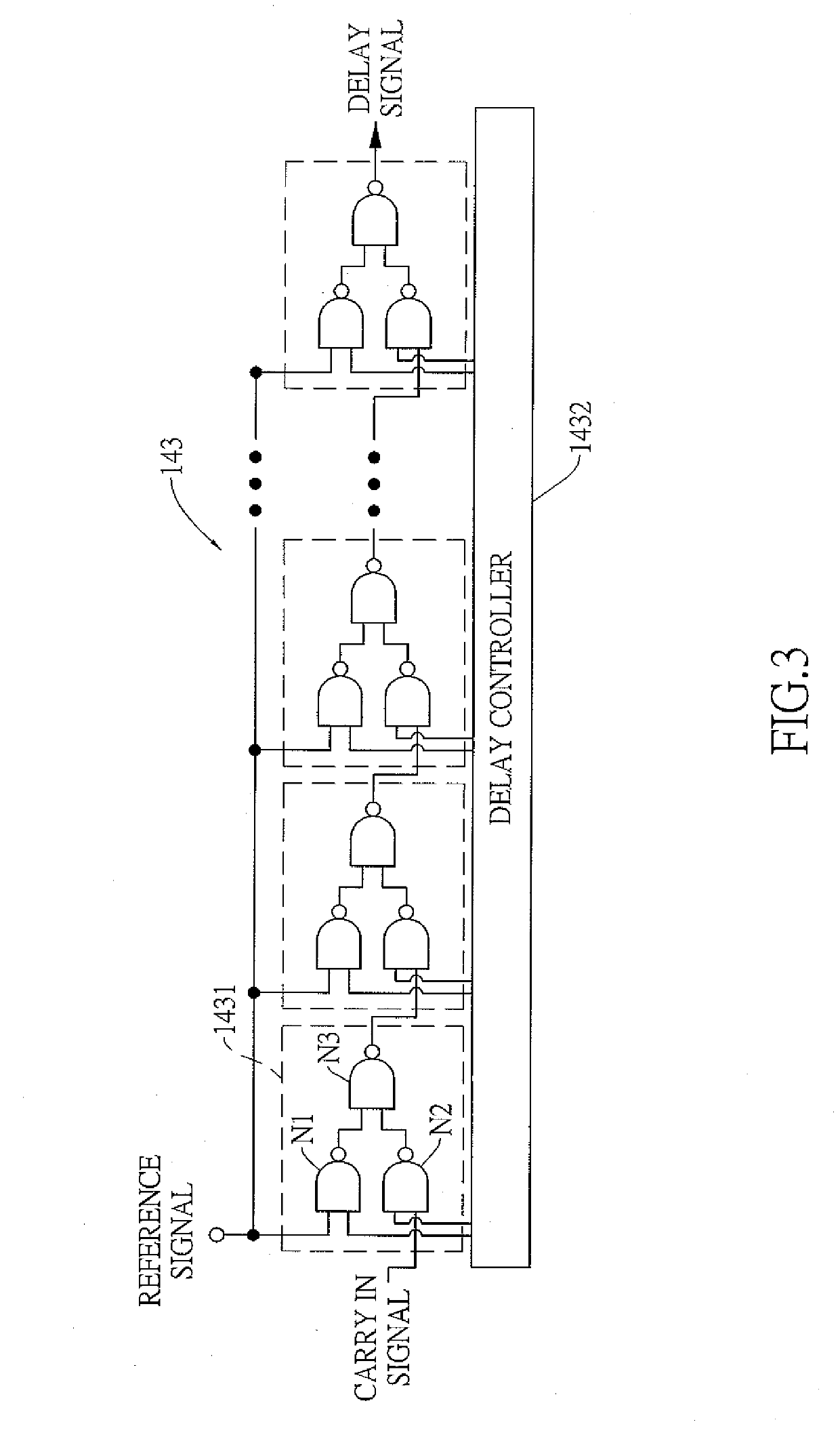
[0044]Further with reference to FIG. 3, the DTC 143 includes a plurality of unit cells 1431 and a delay controller 1432. The unit cells 1431 are connected in series, and each one of the unit cells 1431 includes a first nand gate N1, a second nand gate N2, and a third nand gate N3.

[0045]The first nand gate N1 includes two first inputs and a first output. One of the two first inputs receives the reference signal, and another one of the two first inputs is electrically connected to the delay controller 142.

[0046]The second nand gate N2 includes two second inputs and a second output. One of the two second inputs is electrically connected to the delay controller 142.

[0047]The third nand gate N3 includes two third inputs and a third output. One of the two third inputs is electrically connected to the first output, and another one of the two third inputs is electrically connected to the second output. Another one of the two second inputs is electrically connected to the third output of a p...

second embodiment

[0063]With reference to FIG. 6, the DTC 143 includes at least one unit cell 1431 and a delay controller 1432. The at least one unit cell 1431 includes a delay cell D and a capacitor C.

[0064]The delay cell D includes an input and an output. The input of the delay cell D receives the reference signal, and the output of the delay cell D outputs the delay signal.

[0065]The capacitor C is electrically connected between the output of the delay cell D and a ground.

[0066]The delay controller 1432 is electrically to the SDM 142 and the capacitor C of the at least one unit cell 1431, generates a delay control signal according to the control signal, and outputs the delay control signal to the at least one unit cell to control capacity of the capacitor C.

[0067]When the capacity of the capacitor C is increased, the delay time period of the delay cell D will also increased. Namely, the capacity of the capacitor C can control delay time period of the delay cell D, and a phase difference between the...


PUM


Abstract

A divider-less phase locked loop (PLL) includes a phase frequency detector (PFD), a charge pump (CP), a voltage controlled oscillator (VCO), a delay unit, and a clock gating unit. The PFD is electrically connected to the VCO through the CP, and the CP outputs a voltage control signal to the VCO. The VCO generates an output signal. The delay unit receives and delays a reference signal to generate a delay signal. The clock gating unit samples the output signal according to the delay signal. Since the clock gating unit samples the output signal according to the delay signal, the divider-less PLL does not need to include a divider to divide a frequency of the output signal. Therefore, power consumption of the divider-less PLL can be reduced.

Description

BACKGROUND OF THE INVENTION1. Field of the Invention[0001]The present invention relates to a phase locked loop (PLL), and more particularly to a divider-less PLL.2. Description of the Related Art[0002]With reference to FIG. 12, a phase locked loop (PLL) generally includes a phase frequency detector (PFD) 121, a charge pump (CP) 122, a loop filter (LP) 123, a voltage controlled oscillator (VCO) 124, and a divider 125. The PFD 121 receives two input signals and produces an error signal which is proportional to a phase difference between the two input signals. The PFD 121 outputs the error signal to the CP 122. The CP 122 produces a control signal according to the error signal, and outputs the control signal to the VCO 124 through the LP 123. The VCO 124 produces an output signal with an output frequency according to the control signal.[0003]The divider 125 receives the output signal and produces a feedback signal with a feedback frequency. The PFD 121 receives a reference signal with ...

Claims


Application Information

Patent Timeline
Patent Type & Authority Applications(United States)
IPC IPC(8): H03L7/089H03L7/16H03L7/081
CPCH03L7/0816H03L7/16H03L7/0891H03L7/0818H03L7/113G01S7/352G01S7/40G01S7/4021G01S13/343H03B5/04H03B5/1215H03B2200/004H03B2200/0074H03B2201/0208H03F1/0205H03F1/32H03F3/10H03F3/19H03F3/45475H03F3/45636H03F2200/222H03F2200/451H03F2200/513H03F2203/45156H03F2203/45544H03F2203/45631H03H7/06H03L7/099H04B1/18
Inventor CHEN, PANG-NINGLIN, CHEN-LUNCHEN, YING-CHIAWANG, WEI-JYUNWANG, MIKE CHUN-HUNG
Owner KAIKUTEK INC
Why Eureka
Try Eureka