
Cell culture apparatus and cell culture method

Active Publication Date: 2019-10-24
FUJIFILM CORP
View PDF0 Cites 0 Cited by
  • Summary
  • Abstract
  • Description
  • Claims
  • Application Information

AI Technical Summary

Benefits of technology

The patent describes a cell culture apparatus that can produce a large amount of differentiated cells by continuously carrying out the required processes in a closed system. This reduces the risk of biological contamination and ensures cell homogeneity. The apparatus includes an incubator for maintaining a constant temperature and a temperature gradient-reducing mechanism to prevent temperature differences between the inside and outside of the incubator. Overall, this technology allows for the continuous and efficient production of differentiated cells.

Problems solved by technology

There has been no example proposed so far for a cell culture apparatus which has been able to produce a large amount of differentiated cells by continuously carrying out the series of processes required for the induction of differentiation as described above in a closed system, and it has been considered difficult to increase a culture scale of differentiated cells.

Method used


Image

  • Cell culture apparatus and cell culture method
  • Cell culture apparatus and cell culture method
  • Cell culture apparatus and cell culture method

Examples


first embodiment

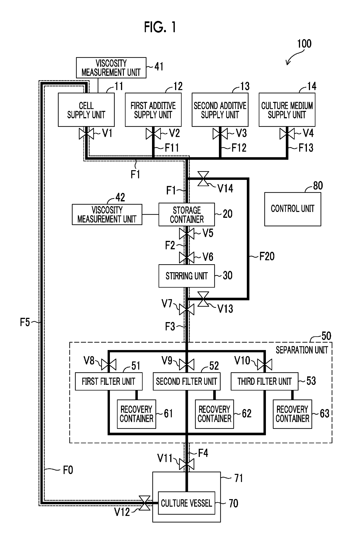
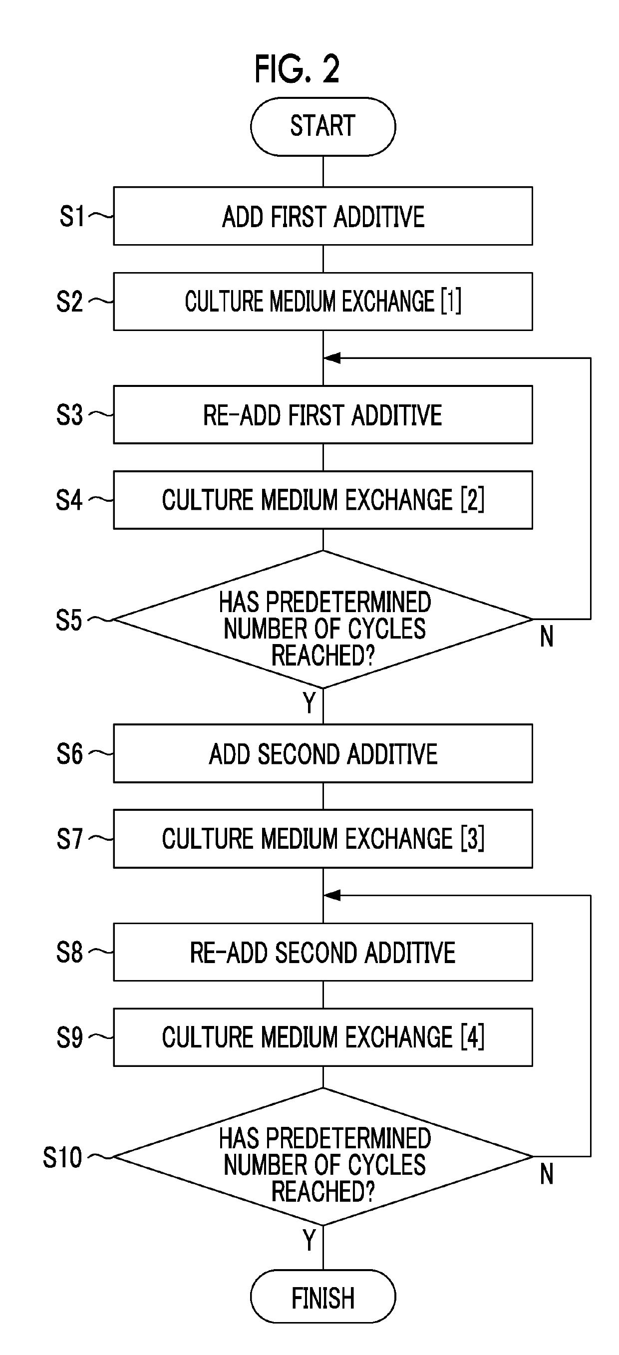
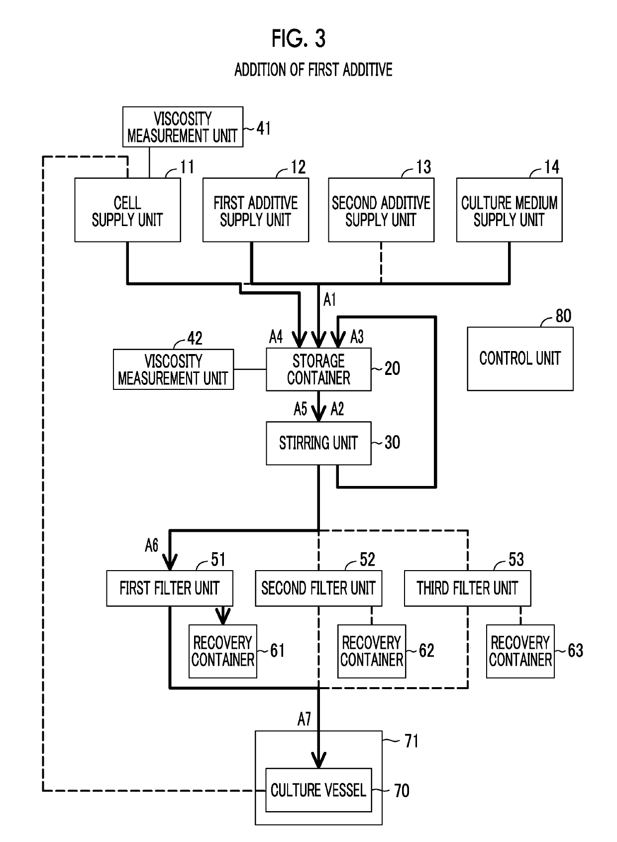
[0046]FIG. 1 is a block diagram showing an example of a configuration of a cell culture apparatus 100 according to the embodiment of the disclosed technology. The cell culture apparatus 100 is a cell culture apparatus that automatically carries out a plurality of processes required to induce the differentiation of pluripotent stem cells into differentiated cells to produce desired differentiated cells.

[0047]Pluripotent stem cells are cells having a self-replication ability and a multilineage potential capable of differentiating into any of ectoderm, mesoderm, and endoderm. Examples of pluripotent stem cells include embryonic stem cells (ES cells), induced pluripotent stem cells (iPS cells), embryonic germ cells (EG cells), embryonal carcinoma cells (EC cells), multipotent adult progenitor cells (MAP cells), adult pluripotent stem cells (APS cells), and Muse cells (multi-lineage differentiating stress enduring cells). Differentiated cells are cells which have specific morphology and ...

second embodiment

[0164]FIG. 11 is a block diagram showing a configuration of a cell culture apparatus 100 A according to a second embodiment of the disclosed technology. In the cell culture apparatus 100 according to the first embodiment, a case where a mixture containing an additive and a fresh culture medium is circulated between the storage container 20 and the stirring unit 30 in order to apply a shear stress to the mixture has been illustrated. The cell culture apparatus 100A according to the second embodiment differs from the cell culture apparatus 100 according to the first embodiment in terms of a liquid feeding path for applying a shear stress to the mixture of an additive and a fresh culture medium.

[0165]The cell culture apparatus 100 A according to the second embodiment has a flow channel F21 connecting the outlet and the inlet of the storage container 20 as the liquid feeding path for applying a shear stress to the mixture of an additive and a fresh culture medium. The control unit 80 ap...

third embodiment

[0171]In the cell culture apparatus according to the embodiment of the disclosed technology, the temperature T1 inside the incubator 71 is kept constant at, for example, 37° C., and the temperature T2 outside the incubator 71 is room temperature (for example 25° C.). Therefore, in a case where the cell suspension is made to flow into the culture vessel 70 accommodated inside the incubator 71 and in a case where the cell suspension is made to flow out of the incubator 71, the cells are subjected to heat shock due to a temperature difference of 12° C. The heat shock may damage the cells.

[0172]FIG. 12 is a diagram showing a partial configuration of a cell culture apparatus according to a third embodiment of the disclosed technology. The cell culture apparatus according to the third embodiment comprises temperature gradient-reducing mechanisms 91 and 92 for reducing the temperature gradient between the inside and the outside of the incubator 71 accommodating the culture vessel 70.

[0173]...


PUM


Abstract

Provided is a cell culture apparatus including a cell supply unit that supplies cells; a culture medium supply unit that supplies a culture medium; an additive supply unit that supplies an additive for inducing the differentiation of undifferentiated cells; a stirring unit that stirs a processing target; a separation unit that separates a component contained in the processing target; a culture vessel that cultures the cells; a first flow channel that forms a circulation route passing through the cell supply unit, the stirring unit, the separation unit, and the culture vessel; a second flow channel that connects the culture medium supply unit and the first flow channel; a third flow channel that connects the additive supply unit and the first flow channel; and a control unit that controls the feeding of liquid through the first flow channel, the second flow channel, and the third flow channel.

Description

CROSS-REFERENCE TO RELATED APPLICATIONS[0001]This application is a continuation application of International Application No. PCT / JP2018 / 001631, filed Jan. 19, 2018, the disclosure of which is incorporated herein by reference in its entirety. Further, this application claims priority from Japanese Patent Application No. 2017-008911, filed Jan. 20, 2017, the disclosure of which is incorporated herein by reference in its entirety.BACKGROUND1. Technical Field[0002]The disclosed technology relates to a cell culture apparatus and a cell culture method.2. Related Art[0003]For example, the following techniques are known as techniques relating to a cell culture apparatus that carries out processing relating to cell culture.[0004]For example, JP2015-100309A discloses a cell management system comprising an automatic culture system having an automatic culture apparatus for automatically culturing cells and a cell management unit for managing information on the state of the cultured cells, a mem...

Claims


Application Information

Patent Timeline
IPC IPC(8): C12M1/34C12N5/074C12M1/12
CPCC12N5/0696C12M41/32C12M41/46C12M37/02C12M41/18C12M41/14C12M47/04C12M33/14C12M23/44C12M29/18C12M29/26C12M41/48C12N5/0657C12N2506/02C12N2506/45C12N2501/415
Inventor TAKAYAMA, HIDETOSHIGOTO, SHUN
Owner FUJIFILM CORP
Learn More