Supercharge Your Innovation With Domain-Expert AI Agents!

Interferometric frequency-swept source and detector in a photonic integrated circuit

Active Publication Date: 2019-11-07
HI LLC
View PDF0 Cites 13 Cited by
  • Summary
  • Abstract
  • Description
  • Claims
  • Application Information

AI Technical Summary

Benefits of technology

The present invention is about a non-invasive optical measurement system that uses a two-dimensional array of photonic integrated circuits (PICs) to measure physiological events in an anatomical structure, such as a brain. The PICs are mechanically coupled to each other and are designed to emit sample light into the anatomical structure and detect the scattered light that comes back. The system can measure changes in the anatomical structure caused by the sample light and can determine the location and depth of the physiological event using optical path length information. The system can also be used to detect fast-optical signals and is minimally invasive, making it suitable for non-invasive optical measurement in brain research.

Problems solved by technology

However, because optical imaging techniques rely on light, which scatters many times inside brain, skull, dura, pia, and skin tissues, the light paths occurring in these techniques comprise random or “diffusive” walks, and therefore, only limited spatial resolution can be obtained by a conventional optical detector, often on the order of centimeters, with usable penetration depths being limited to a few millimeters.
The reason for this limited spatial resolution is that the paths of photons striking the detector in such schemes are highly variable and difficult, and even impossible, to predict without detailed microscopic knowledge of the scattering characteristics of the brain volume of interest, which is typically unavailable in practice (i.e., in the setting of non-invasive measurements through skull for detecting neural activity in the brain for brain-computer interfacing).
In summary, light scattering has presented challenges for optical detection techniques in achieving high spatial resolution deep inside tissue.
Moreover, the diffusive nature of light propagation also creates challenges for measurements of fast changes in optical scattering inside tissue, since essentially all paths between source and detector are highly scattered to begin with.
Regardless of the type, the depth at which an OCT system images biological tissue is limited, because at greater depths the proportion of light that escapes without scattering (i.e., the ballistic light) is too small to be detected.
Thus, the clinical applications of OCT have, thus far, been limited to imaging sub-surface features, such as obtaining high-resolution ophthalmic images of the retina.
As such, OCT is presently insufficient for measuring neural activity in the deeper regions of the brain (i.e., deeper than 2 mm).
Furthermore, the systems described above have not been demonstrated to measure fast-optical signals, which refers to changes in optical scattering that occur when light propagating through active neural tissue (e.g., active brain tissue) is perturbed through a variety of mechanisms, including, but not limited to, cell swelling, cell volume change, changes in membrane potential, changes in membrane geometry, ion redistribution, birefringence changes, etc.
Although traditional OCT and state of the art iNIRS systems are sufficient for their intended purposes, these techniques utilize holographic methods, mixing the detected light against a reference beam, thereby requiring a relatively complicated and expensive arrangement of components.
Reference beams are notoriously challenging to keep stable in a stationary device, let alone a device that may be attached to a moving human body during operation, so a solution to this issue of stability is required to use OCT or iNIRS as a diagnostic tool.
Further, while the iNIRS and OCT approaches are very sophisticated, they both require the detection and measurement of speckles, presenting challenges in a highly attenuating medium, such as the human body, due to the very low number of photons that reach each detector.
Thus, a very large number of detectors (or pixels) are required to individually detect the speckles, thereby further increasing the complexity and expense of the system.

Method used


Image

  • Interferometric frequency-swept source and detector in a photonic integrated circuit
  • Interferometric frequency-swept source and detector in a photonic integrated circuit
  • Interferometric frequency-swept source and detector in a photonic integrated circuit

Examples


Embodiment Construction

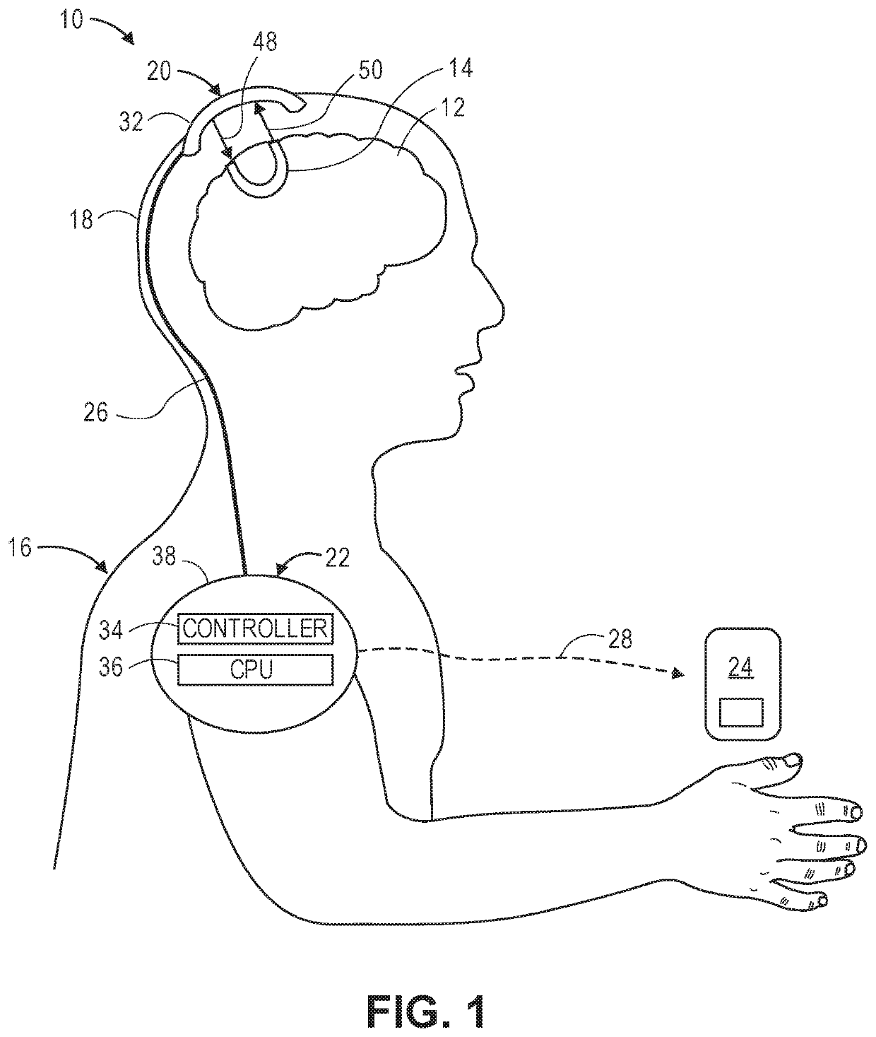
[0051]Referring first to FIG. 1, one embodiment of a non-invasive optical measurement system 10 constructed in accordance with the present inventions will now be described. The non-invasive optical measurement system 10 will be described as a swept-source holographic optical system (i.e., a system that mixes detected light against a reference beam in order to increase the signal-to-noise ratio (SNR) of the relevant signal), and in particular a Near-Infrared Spectroscopy (iNIRS) system. In alternative embodiments, the non-invasive optical measurement system 10 may take the form of other swept-source holographic optical systems, such as a Swept-Source Optical Computed Tomography (SS-OCT). In still other embodiments, the non-invasive optical measurement system 10 may take the form of a non-holographic optical system.

[0052]In any event, the non-invasive optical measurement system 10 is designed to non-invasively acquire physiological-encoded data (i.e., data representative of a physiolo...


PUM


Abstract

A non-invasive optical measurement system comprises a two-dimensional array of photonic integrated circuits (PICs) mechanically coupled to each other. Each PIC is configured for emitting sample light into an anatomical structure, such that the sample light is scattered by the anatomical structure, resulting in physiological-encoded signal light that exits the anatomical structure. Each PIC is further configured for detecting the signal light. The non-invasive optical measurement system further comprises processing circuitry configured for analyzing the detected signal light from each of the PICs, and based on this analysis, determining an occurrence and a three-dimensional spatial location of the physiological event in the anatomical structure.

Description

RELATED APPLICATION DATA[0001]Pursuant to 35 U.S.C. § 119(e), this application claims the benefit of U.S. Provisional Patent Application Ser. No. 62 / 666,940, filed May 4, 2018, and U.S. Provisional Patent Application Ser. No. 62 / 692,124, filed Jun. 29, 2018, which are expressly incorporated herein by reference.FIELD OF THE INVENTION[0002]The present inventions relate to methods and systems for non-invasive measurements in the human body, and in particular, methods and systems related to detecting physiologically-dependent optical parameters in the human body, .e.g., the brain.BACKGROUND OF THE INVENTION[0003]Measuring neural activity in the brain is useful for medical diagnostics, neuromodulation therapies, neuroengineering, or brain-computer interfacing.[0004]Conventional methods for measuring neural activity in the brain include diffusive optical imaging techniques, which employ moderate amounts of near-infrared or visible light radiation, thus being comparatively safe and gentle ...

Claims


Application Information

Patent Timeline
IPC IPC(8): A61B5/00G01B11/02G01B11/22
CPCG01B11/22A61B5/0059G01B11/02A61B5/4064A61B5/0082A61B5/14552A61B5/14553A61B2562/0233A61B2562/046A61B5/7228A61B5/0042A61B2576/026A61B5/0066A61B5/6814G16H30/40
Inventor HORSTMEYER, ROARKEZHOU, HAOJIANGRUAN, HAOWENSHEN, YUECHENGALFORD, JAMU
Owner HI LLC
Features
  • R&D
  • Intellectual Property
  • Life Sciences
  • Materials
  • Tech Scout
  • Unparalleled Data Quality
  • Higher Quality Content
  • 60% Fewer Hallucinations
Learn More