Un-supervised convolutional neural network for distortion map estimation and correction in MRI

a convolutional neural network and distortion map technology, applied in the field of magnetic resonance imaging, can solve the problems of significant reduction of computational time and difficult to obtain real-life data, and achieve the effect of facilitating the use of a blip up/down scheme, reducing computational time, and reducing processing tim

Active Publication Date: 2020-01-16
THE BOARD OF TRUSTEES OF THE LELAND STANFORD JUNIOR UNIV
View PDF0 Cites 11 Cited by
  • Summary
  • Abstract
  • Description
  • Claims
  • Application Information

AI Technical Summary

Benefits of technology

[0006]The present invention provides a method for estimating a distortion map for EPI distortion correction that is an order of magnitude faster than state of the art iterative methods. This approach reduces the processing time to a few seconds per volume, which is significantly faster than iterative approaches like FSL's topup which takes around to min on the same machine. This approach results in a correction accuracy that is virtually identical to the optimum found by an iterative search, but with significantly reduced computational time. This facilitates the use of a blip up / down scheme for all diffusion-weighted acquisitions and potential real-time EPI distortion correction without sacrificing accuracy.
[0008]The CNN is preferably trained on a wide variety of different diffusion weighted to spin echo EPI protocols. Instead of training the CNN using ground truth distortion maps, the CNN is trained to minimize a similarity metric (loss function) between corrected up and down images. This approach allows the CNN to be trained without the need for a ground truth distortion map, which is difficult to get for real life data, or may not be guaranteed to represent a “true” ground truth.

Problems solved by technology

This approach results in a correction accuracy that is virtually identical to the optimum found by an iterative search, but with significantly reduced computational time.
This approach allows the CNN to be trained without the need for a ground truth distortion map, which is difficult to get for real life data, or may not be guaranteed to represent a “true” ground truth.

Method used


Image

  • Un-supervised convolutional neural network for distortion map estimation and correction in MRI
  • Un-supervised convolutional neural network for distortion map estimation and correction in MRI
  • Un-supervised convolutional neural network for distortion map estimation and correction in MRI

Examples


Embodiment Construction

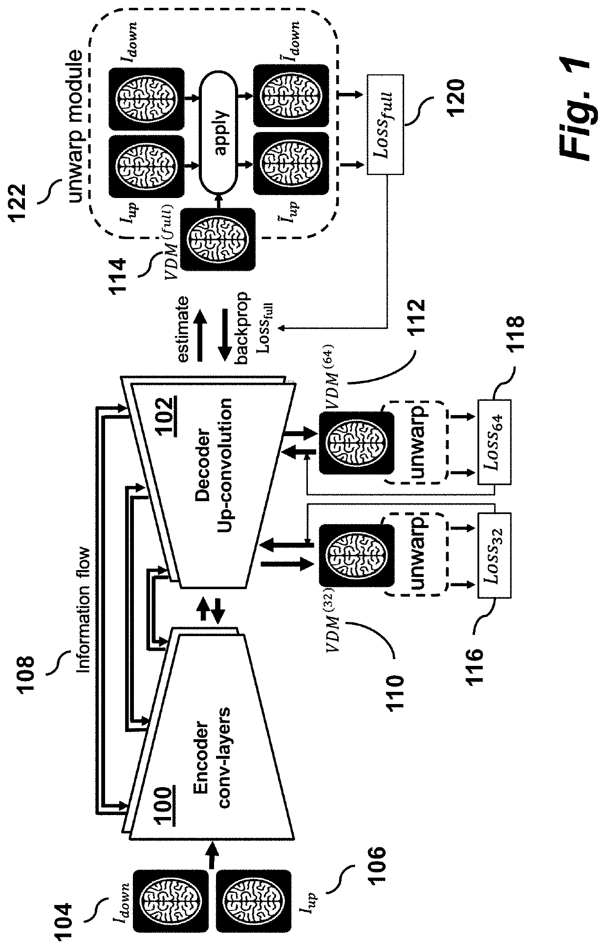
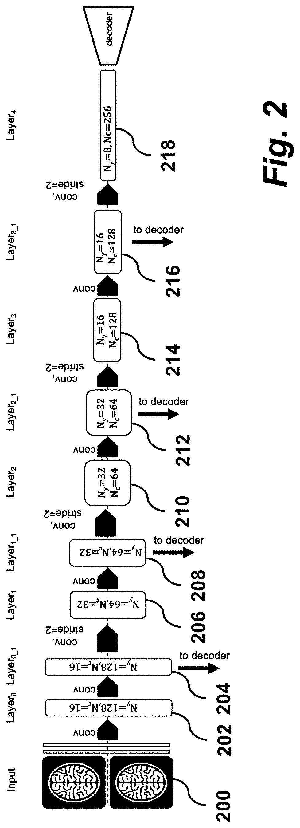
[0020]FIG. 1 shows a processing pipeline and associated network architecture illustrating a method of distortion map estimation according to an embodiment of the invention. An unsupervised deep convolutional neural net has a U-Net (Ronneberger et al., 2015) architecture with an encoder section 100 and a decoder section 102. The input to the encoder 100 is an up / down image pair 104, 106 denoted Iup and Idown and represented as a Nx×Ny×2 tensor. The input images Iup and Idown are down-sampled to a 64×64 and to a 32×32 grid as a pre-processing step. Then the full resolution up / down pair is propagated through the encoder network 100 with a series of convolution layers with decreasing feature map dimensions. As the feature map dimension is decreased, the number of channels is increased between layers resulting in an 8×8 map with Nc=256 channels.

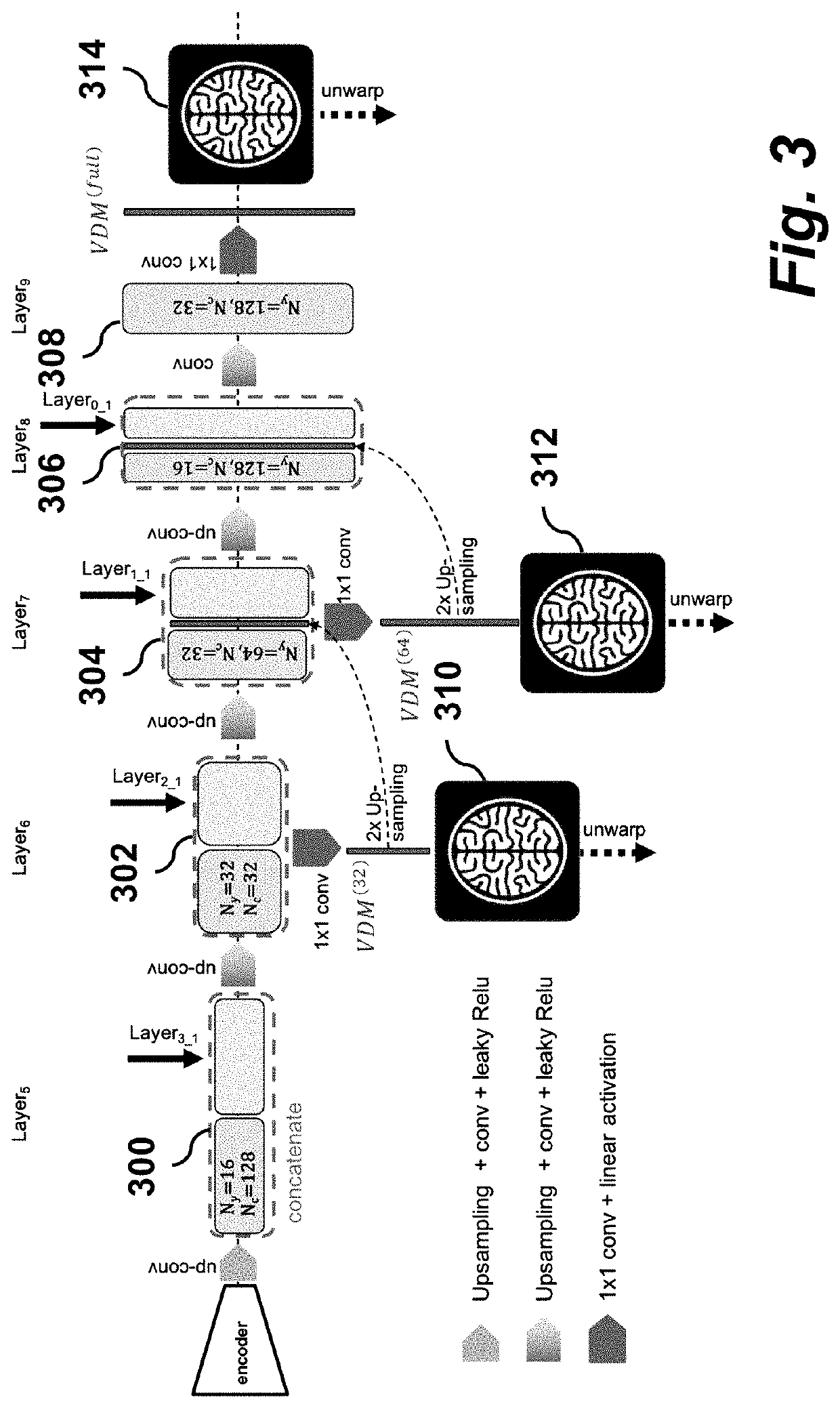
[0021]The final feature map (8×8×Nc) of the encoder 100 is fed into a decoder 102 network where the full image resolution is gradually restored b...


PUM


Abstract

A method for magnetic resonance imaging (MRI) includes performing an echo planar imaging acquisition using inverted up / down phase encoding directions and reconstructing acquired images having geometric distortions along the phase encoding directions due to off-resonant spins; feed-forward estimating by a convolutional neural network (CNN) a phase distortion map from the acquired images; where the CNN is trained to minimize a similarity metric between un-warped up / down image pairs; and performing geometric distortion correction of the acquired images using the phase distortion map to unwarp the acquired images.

Description

CROSS-REFERENCE TO RELATED APPLICATIONS[0001]This application claims priority from U.S. Provisional Patent Application 62 / 696,235 filed Jul. 10, 2018, which is incorporated herein by reference.STATEMENT REGARDING FEDERALLY SPONSORED RESEARCH OR DEVELOPMENT[0002]None.FIELD OF THE INVENTION[0003]The present invention relates generally to magnetic resonance imaging. More specifically, it relates to techniques for geometric distortion correction of echo planar image data.BACKGROUND OF THE INVENTION[0004]In echo planar imaging (EPI), geometric distortions are deviations from rectilinear mapping caused by a combination of local off-resonances, i.e., shim imperfections combined with the relatively low readout bandwidth of an EPI train along the phase encode direction which results in a spatial shift of the reconstructed voxel along that direction. Geometric distortions can lead to errors when registering functional or diffusion-weighted imaging data to an undistorted anatomical scan and li...

Claims


Application Information

Patent Timeline
Patent Type & Authority Applications(United States)
IPC IPC(8): G06T5/00G06N3/04G06F17/15
CPCG06N3/04G06F17/15G06T5/006G06T2207/10088G06T2207/20084G06N3/084G06N3/082G06N3/088G06N3/048G06N3/045G06T7/0012
Inventor ZAHNEISEN, BENJAMINFLEISCHMANN, DOMINIKBAEUMLER, KATHRIN
Owner THE BOARD OF TRUSTEES OF THE LELAND STANFORD JUNIOR UNIV
Why Eureka
Try Eureka