
Phase analog coherent demodulation system and method for phase sensitive optical time domain reflectometry

a coherent demodulation and phase analog technology, applied in the field of distributed optical fiber vibration sensors, can solve the problems of not actually reducing the processing speed of hardware and software required by the system, affecting and affecting the accuracy of the charging process, so as to improve the convenience and safety of the charging process.

Active Publication Date: 2020-01-16
ZHEJIANG JERICORE TECH CO LTD
View PDF4 Cites 7 Cited by
  • Summary
  • Abstract
  • Description
  • Claims
  • Application Information

AI Technical Summary

Benefits of technology

The patent describes a system and method for more efficient and cost-effective demodulation in optical time domain reflectometry. The system provides a mobile power supply that improves user convenience and safety in the charging process. Additionally, the system reduces the frequency required for quadrature demodulation and improves stability, allowing for easier implementation.

Problems solved by technology

The backward scattered light intensity detection technology is simple and easy to implement, but is subject to the polarization of scattered light, noise of State system and other factors, and only qualitative detection of vibration signals can be realized.
However, digital coherent detection technology requires high-speed data acquisition and processing to ensure signal integrity, which is expensive, and imposes high requirements on both hardware and software, making it difficult to implement.
The method does not actually reduce the processing speed of the hardware and software required by the system, and the implementation is still difficult.

Method used


Image

  • Phase analog coherent demodulation system and method for phase sensitive optical time domain reflectometry
  • Phase analog coherent demodulation system and method for phase sensitive optical time domain reflectometry
  • Phase analog coherent demodulation system and method for phase sensitive optical time domain reflectometry

Examples


Embodiment Construction

[0026]In the following, the invention is further described with reference to the drawings and specific embodiments. It should be noted that, without conflict, any combination of the embodiments or the features may form a new embodiment.

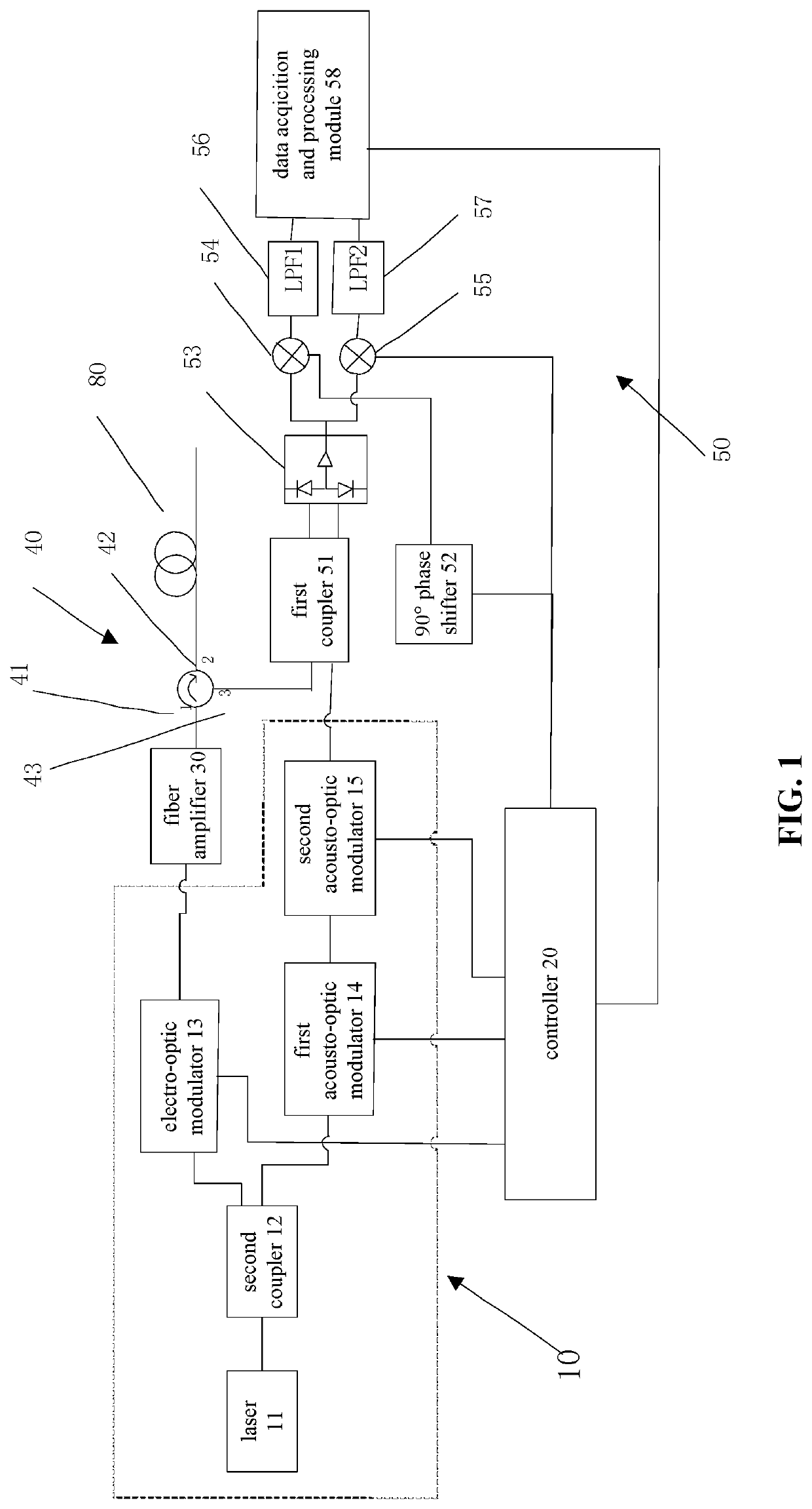
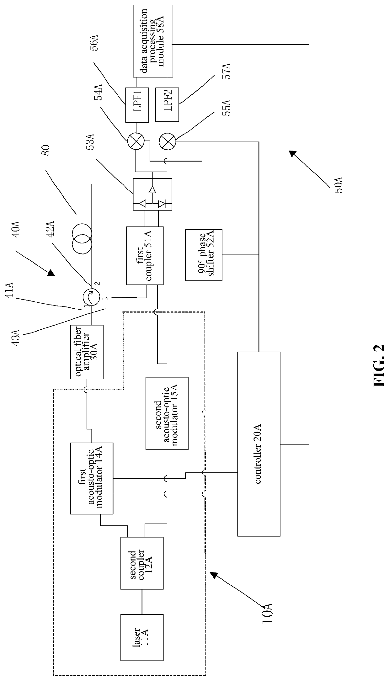
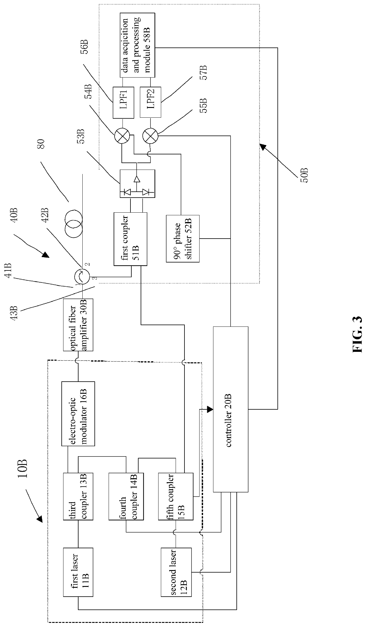
[0027]Referring to FIG. 1, a phase analog coherent demodulation system for phase sensitive optical time domain reflectometry in accordance with an embodiment will be illustrated in the following description. The phase analog coherent demodulation system for phase sensitive optical time domain reflectometry comprises a difference frequency and pulse generator 10, a controller 20, an optical fiber amplifier 30, a three-port optical circulator 40 and an I / Q demodulation module 50.

[0028]The difference frequency and pulse generator 10 is configured to generate two different pulses of pulsed light and continuous light.

[0029]The controller 20 is electrically connected to the difference frequency and pulse generator 10, and the controller 20 generates the fre...


PUM


Abstract

A phase analog coherent demodulation system includes a difference frequency and pulse generator configured to generate a pulsed light and a continuous light with different frequency from the pulsed light, a controller, and an I / Q demodulation module. The controller locks the frequency difference signal of the pulse light, and the pulsed light generates the backward scattered light of constant frequency in the measured medium, and the backward scattered light returns along the original path and mixing beat with the continuous light in the I / Q demodulation module, the difference frequency electrical signals of the two optical signals are obtained. The I / Q demodulation module orthogonally demodulates the difference frequency electrical signal by using the frequency difference signal of the pulsed light and the continuous light as the fundamental frequency signal of the orthogonal demodulation, to detect phase information of the vibration signal. The invention reduces the operating frequency required for quadrature demodulation in system phase detection.

Description

CROSS REFERENCE TO RELATED APPLICATIONS[0001]This non-provisional patent application claims priority under 35 U.S.C. § 119 from Patent Application No. 201810489209.7 filed in The People's Republic of China on May 21, 2018.FIELD OF THE INVENTION[0002]The disclosure relates to distributed optical fiber vibration sensors, and more particularly to a phase analog coherent demodulation system and method for a phase sensitive optical time domain reflectometry.BACKGROUND OF THE INVENTION[0003]Phase sensitive optical time domain reflectometry (φ-OTDR) enables vibration monitoring along the sensing optical fiber by injecting high-coherence narrow-line wide pulse light into the sensing optical fiber and receiving and analyzing the backward Rayleigh scattering signal. It has the advantages of long monitoring distance, high sensitivity, low resource consumption and anti-electromagnetic interference. It plays an important role in the intrusion monitoring and detection of important security sites ...

Claims


Application Information

Patent Timeline
IPC IPC(8): H04B10/548H04L27/22
CPCH04B10/548H04L27/22H04L27/364G01H9/004H04B10/071
Inventor LIU, HANGJIEXIE, YIMINHU, YIBO
Owner ZHEJIANG JERICORE TECH CO LTD
Learn More