
Cantilever sensors for molecule detection

a cantilever sensor and sensor array technology, applied in the field of cantilever sensors and cantilever sensor arrays, can solve the problems of tedious optimization, long passivating of the underside of the cantilever to prevent unwanted ligand adsorption, and the improvement of the sensitivity and selectivity of the cantilever is not finished, so as to improve the selectivity and sensitivity, and improve the sensitivity. , the effect of improving the selectivity

Active Publication Date: 2020-01-30
3P SENSE LTD
View PDF0 Cites 0 Cited by
  • Summary
  • Abstract
  • Description
  • Claims
  • Application Information

AI Technical Summary

Benefits of technology

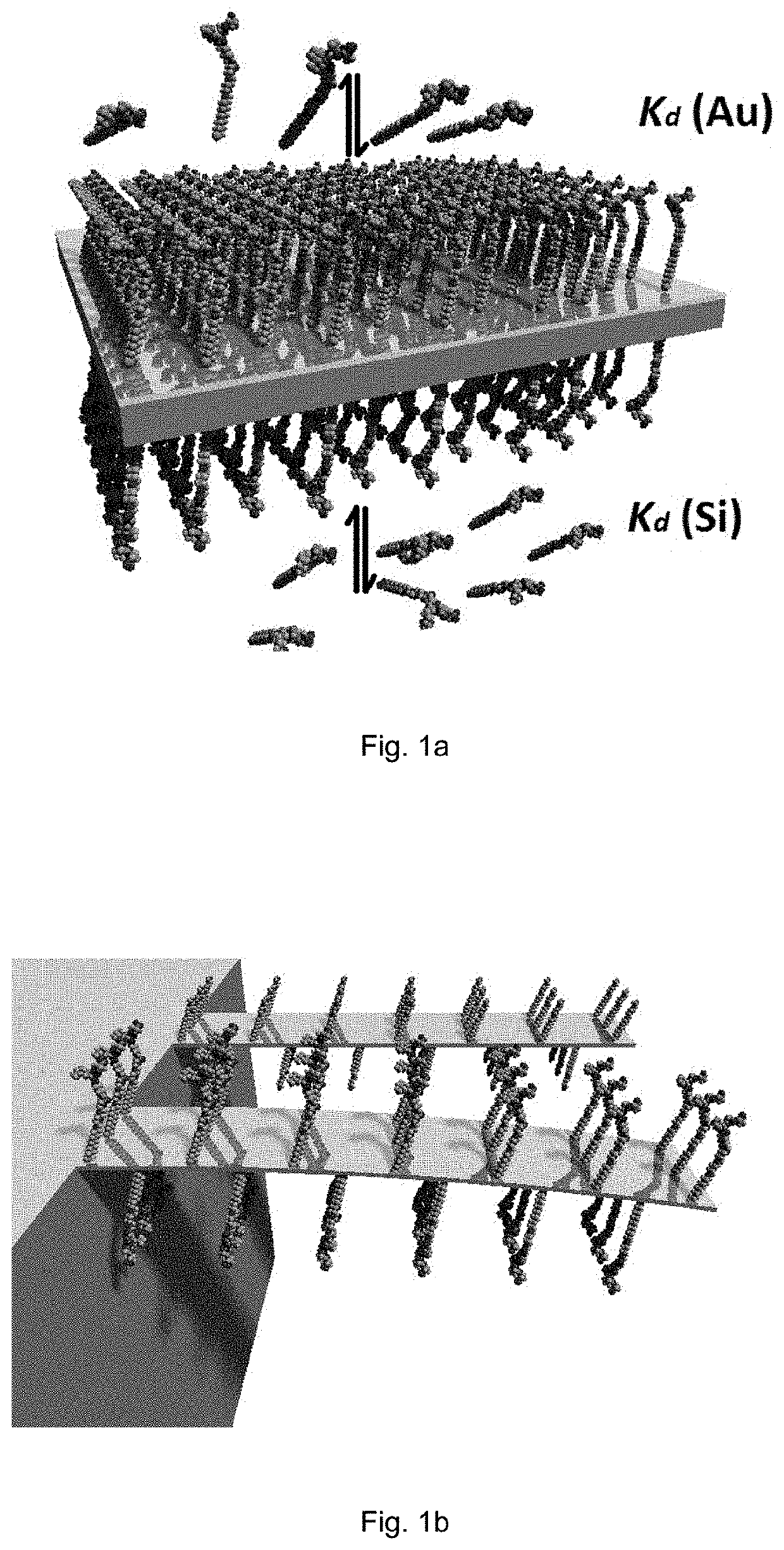
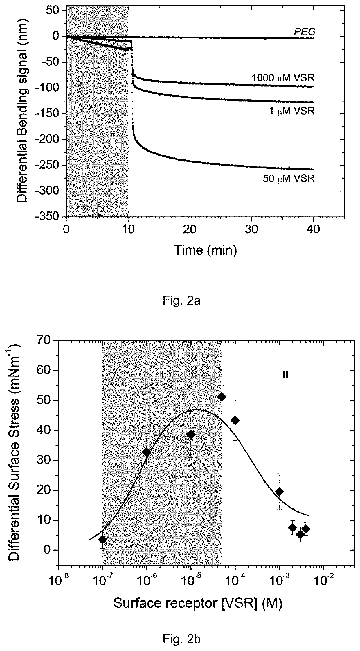
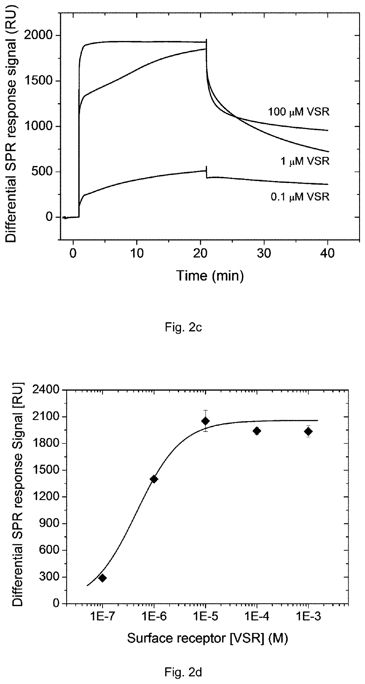
[0015]By tuning the probe molecule concentration (i.e. by working in a concentration range of 1 to 1000 μM), the impact of the underlying surface SAM functionalization can be minimized.
[0017]The process of the disclosure therefore yields a cantilever having the same or even an enhanced selectivity and sensitivity with respect to the known passivated cantilevers without the drawbacks of the passivation procedure (which is lengthy and often requires tedious optimization).
[0018]In another aspect, the disclosure provides a method for detecting molecules in body fluids having improved selectivity and sensitivity.

Problems solved by technology

However, improvements in cantilever sensitivity and selectivity are far from finished and there is still a long felt need in the sector of label-free molecular detection.
Passivating of the underside of the cantilever to prevent unwanted ligand adsorption is lengthy and often requires tedious optimization.
Moreover, the detailed investigation of Si surface passivation shows that the process of cantilever underside coating to prevent unwanted adsorptions is far from complete and therefore needs further optimization.

Method used


Image

  • Cantilever sensors for molecule detection
  • Cantilever sensors for molecule detection
  • Cantilever sensors for molecule detection

Examples


examples

[0079]Cantilever Metal Coating

[0080]Cantilever chips fabricated from Si (100) by IBM Research Laboratory, RUschlikon, Switzerland were first cleaned with freshly prepared piranha solution (ratio 1:1 H2SO4 and H2O2) for 20 min. Arrays were then thoroughly rinsed in deionized water before immersing in the second freshly prepared piranha solution for another 20 min, and again rinsed thoroughly with deionized water. Finally, the arrays were rinsed with pure ethanol and dried on a hotplate at 70° C. for 20 seconds. They were then inspected using the optical microscope to confirm their cleanliness before transferred to the evaporation chamber (BOC Edwards Auto 500, U.K.) for an overnight pumping. One side of the silicon cantilever surface was metalized using an electron beam evaporation with a 2 nm Ti adhesion layer followed by 20 nm of Au at a base pressure of ˜3×10⁻⁷ mbar, and at an evaporation rate of 0.02 nm / s for Ti and Au, respectively, as measured directly above the source by a qua...


PUM

PropertyMeasurementUnit
surface areaaaaaaaaaaa
thicknessaaaaaaaaaa
thicknessaaaaaaaaaa

Abstract

A method of preparing a cantilever sensor for measuring biochemical interactions and their associated stress wherein a cantilever having two sides is coated on one side with at least a gold layer and both sides of the cantilever are functionalized with a self-assembled monolayer (SAM) of a probe molecule by incubating the cantilever in a solution having a concentration of the probe molecule of between 1 to 1000 μM. The unpassivated cantilever sensor comprising a layer coated on one side with a coating comprising gold and being unpassivated on the opposite side, wherein both surfaces comprises a self-assembled monolayer of a probe molecule in which the surface area occupied per probe molecule varies in the range 0.4-1.5 nm2, enabling the stress at the gold top surface that is not cancelled out by a counter stress from the bottom surface so that accurate quantitation of a target molecule is achieved.

Description

RELATED APPLICATION[0001]This application is a Divisional Application of U.S. patent application Ser. No. 15 / 191,056, filed Jun. 23, 2016, which is herein incorporated by reference in its entirety.TECHNICAL FIELD[0002]The present invention relates to cantilever sensors and cantilever sensor arrays having enhanced selectivity and sensitivity for the detection of molecules in body fluids.BACKGROUND ART[0003]Cantilever sensors have attracted considerable attention over the last decade because of their potential as a highly sensitive sensor platform for high throughput and multiplexed detection of proteins, nucleic acids and other molecules.[0004]Biological specificity in detection is typically achieved by immobilizing selective receptors or probe molecules on one side of the cantilever using surface functionalization processes.[0005]Biomolecular interaction between the immobilized receptors or probes and a coupling molecule in a body fluid causes a measurable bending of the cantilever....

Claims


Application Information

Patent Timeline
Patent Type & Authority Applications(United States)
IPC IPC(8): G01N33/53C23C14/02C23C14/16C23C14/30C23C14/58C23C26/00G01N33/543G01N33/552G01N33/553
CPCG01N33/5308G01N33/553C23C14/025G01N33/5306G01N33/552G01N33/54373C23C26/00C23C14/58G01N2333/51C23C14/16C23C14/30G01N33/54393C23C14/021
Inventor NDIEYIRA, JOSEPH WAFULAPATIL, SAMADHANMAZZA, GIUSEPPEPINZANI, MASSIMO
Owner 3P SENSE LTD
Learn More