

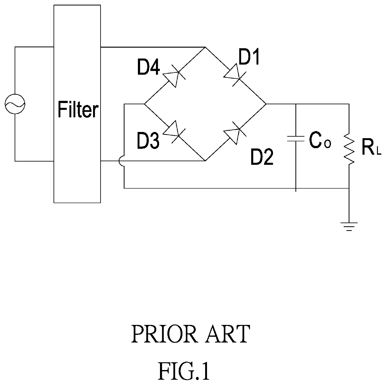
High-frequency half-wave rectifier system of low-harmonicity and high-efficiency
- Summary
- Abstract
- Description
- Claims
- Application Information
AI Technical Summary
Benefits of technology
Problems solved by technology
Method used
Image

Examples
Embodiment Construction
[0023]The following descriptions are exemplary embodiments only, and are not intended to limit the scope, applicability or configuration of the invention in any way. Rather, the following detailed description provides a convenient illustration for implementing exemplary embodiments of the invention. Various changes to the described embodiments may be made in the function and arrangement of the elements described without departing from the scope of the invention as set forth in the appended claims.
[0024]The foregoing and other aspects, features, and utilities of the present invention will be best understood from the following detailed description of the preferred embodiments when read in conjunction with the accompanying drawings.
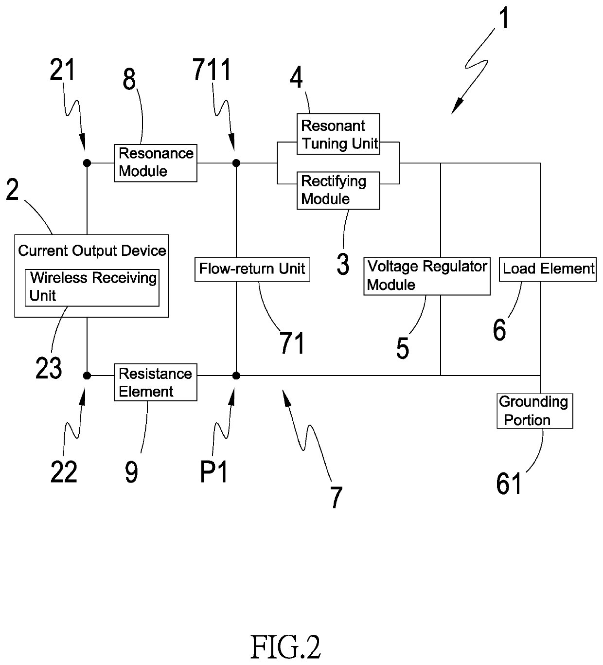
[0025]As shown in FIG. 2, the high-frequency half-wave rectification system 1 of the present invention mainly comprises: a current output device 2 having an output end 21 and a first flow-return end 22 respectively at both ends for outputting alternating cur...
PUM
 Abstract
Description
Claims
Application Information