Supercharge Your Innovation With Domain-Expert AI Agents!

Excitation light source apparatus and optical transmission system

a light source and optical transmission technology, applied in the field of excitation light source apparatus and optical transmission system, can solve the problems of transmission error or prevention of relay distance elongation, transmission error or transmission error, and simultaneous emission optical noise generated by optical amplification, etc., and achieve the effect of simple configuration and gain control

Active Publication Date: 2020-02-06
MITSUBISHI ELECTRIC CORP
View PDF0 Cites 0 Cited by
  • Summary
  • Abstract
  • Description
  • Claims
  • Application Information

AI Technical Summary

Benefits of technology

The present invention allows for control of gain while considering the impact of noise light caused by Raman amplification. This control can be achieved with a simple configuration.

Problems solved by technology

On the other hand, in the optical amplifier such as the EDFA and the Raman amplifier, spontaneous emission optical noise is generated with the optical amplification, in principle.
A transmission error can occur, when the optical amplification control is performed on the basis of the signal light level including the noise light component (the summation of the main signal light level and the noise light level).
For example, if the main signal light level is low and the noise light level is high, the light level necessary for a downstream station to receive the main signal is not ensured, resulting in occurrence of a transmission error or prevention of relay distance elongation, when the main signal light level to be transmitted is assumed to be sufficiently amplified and is transmitted to the downstream station.
In order to perform this process, computation such as logarithmic transformation is necessary, and thus an expensive control device with high processing ability is necessary.
Further, even the Raman amplifier that includes such a database of large capacity has a problem of requiring a complicated process for selecting an optimal value from the database (reference table).
However, in the optical amplifier described in patent reference 2, since it is necessary to output the Raman excitation light to the transmission path while the signal light is not transmitted to the transmission path, a process for interrupting reception of the signal light is forced while the signal light is transmitted to the transmission path, and there is a problem of a complicated process of starting the optical amplifier.
Further, in the optical amplifier described in patent reference 2, it is necessary to measure the correlative relationship between the excitation light intensity and the noise light generation amount, and there is a problem of requiring complicated control.
Further, when the light level is expressed as a logarithmic value [dBm], it is necessary to subtract the noise light level [dBm] measured in advance, from the light level [dBm] amplified by the Raman excitation light, in order to perform the noise light correction, and thus an expensive control device with high processing ability for performing computation such as logarithmic transformation is necessary.

Method used


Image

  • Excitation light source apparatus and optical transmission system
  • Excitation light source apparatus and optical transmission system
  • Excitation light source apparatus and optical transmission system

Examples


first embodiment

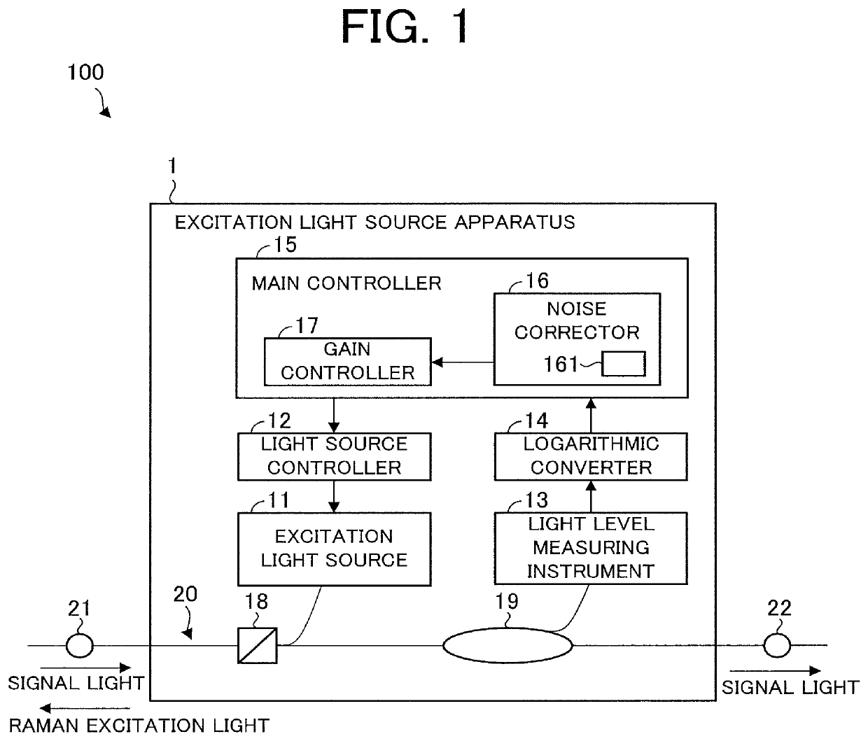
[0035]FIG. 1 is a block diagram schematically illustrating a configuration example of an optical transmission system 100 that includes an excitation light source apparatus 1 according to a first embodiment of the present invention. The optical transmission system 100 includes an excitation light source apparatus 1 and a transmission path 20.

[0036]The excitation light source apparatus 1 illustrated in FIG. 1 includes an excitation light source 11, a light source controller 12, a light level measuring instrument 13, a logarithmic converter 14, a main controller 15, a multiplexer 18, and a branching device 19. In the present embodiment, the excitation light source apparatus 1 is a Raman amplifier.

[0037]The multiplexer 18 and the branching device 19 are connected to each other by the transmission path 20. In the present embodiment, the transmission path 20 is an optical fiber. However, it may be a light transmission path that is not the optical fiber.

[0038]The excitation light source ap...

second embodiment

[0138]An excitation light source apparatus 2 according to a second embodiment differs from the excitation light source apparatus 1 according to the first embodiment in that a main controller 215 does not include the noise corrector 16, and both of them are the same with each other in other points. However, the reference table 161 is provided in a gain controller 217 of the main controller 215.

[0139]With regard to the configuration and operation of the excitation light source apparatus 2 according to the second embodiment, the points that differ from the configuration and operation of the excitation light source apparatus 1 according to the first embodiment will be mainly described.

[0140]FIG. 8 is a block diagram schematically illustrating a configuration example of an optical transmission system 200 that includes the excitation light source apparatus 2 according to the second embodiment. The optical transmission system 200 includes an excitation light source apparatus 2 and a transm...

third embodiment

[0166]An excitation light source apparatus 3 according to a third embodiment includes a main controller 315 instead of the main controller 15 of the excitation light source apparatus 1 according to the first embodiment, and differs from the excitation light source apparatus 1 according to the first embodiment in including a light source controller 312 instead of the light source controller 12 of the excitation light source apparatus 1, and both of them are the same with each other in other points. Specifically, the main controller 315 includes a gain controller 317 and a noise corrector 16.

[0167]Points of difference between the configuration and operation of the excitation light source apparatus 3 according to the third embodiment and the configuration and operation of the excitation light source apparatus 1 will be mainly described.

[0168]FIG. 10 is a block diagram schematically illustrating a configuration example of an optical transmission system 300 that includes the excitation l...


PUM


Abstract

An excitation light source apparatus includes: an excitation light source to generate Raman excitation light in a drive state and to stop generating the Raman excitation light in a stop state; a light source controller to control the intensity of the Raman excitation light in the drive state; a light level measuring instrument to measure the light level of signal light; a logarithmic converter to convert at least one measurement result of measuring by the light level measuring instrument to a logarithmic value; and a main controller to decide a correction value based on the logarithmic value of the at least one measurement result in the stop state. The main controller controls the light source controller by using the correction value and a preset gain control target value.

Description

TECHNICAL FIELD[0001]The present invention relates to an excitation light source apparatus that outputs Raman excitation light for amplifying signal light and an optical transmission system including this excitation light source apparatus.BACKGROUND ART[0002]In general, an amplification device (optical amplifier) that amplifies a light signal by utilizing Raman amplification is introduced to elongate a relay distance, in a wavelength division multiplexing optical transmission system that transmits, over a long distance, a light signal (signal light) to which wavelength division multiplexing (WDM: Wavelength Division Multiplexing) is performed. This amplification device amplifies the signal light by outputting Raman excitation light to a transmission path to compensate for level reduction caused by transmission, thereby making it possible to elongate the relay distance. The level reduction mentioned here means that the light level (signal light level) of the signal light decreases ac...

Claims


Application Information

Patent Timeline
IPC IPC(8): H04B10/291H04B10/293
CPCH04B10/2916H01S3/302H04B10/293G02F1/35
Inventor IMANISHI, KATSUNORITOKURA, TOSHIYUKICHIKAMORI, SHUNTAKATA, KENGO
Owner MITSUBISHI ELECTRIC CORP
Features
  • R&D
  • Intellectual Property
  • Life Sciences
  • Materials
  • Tech Scout
  • Unparalleled Data Quality
  • Higher Quality Content
  • 60% Fewer Hallucinations
Learn More