Connector-based high-voltage lockout function

a high-voltage lockout and connector technology, applied in the direction of secondary cell servicing/maintenance, coupling device connection, safety/protection circuit, etc., can solve the problems of high-voltage bus de-energized and disconnectress, and achieve simplified and robust connector-based, reduce high-voltage power exposure, and reduce dependence

Active Publication Date: 2020-02-13
GM GLOBAL TECH OPERATIONS LLC
View PDF0 Cites 3 Cited by
  • Summary
  • Abstract
  • Description
  • Claims
  • Application Information

AI Technical Summary

Benefits of technology

[0002]Regardless of nominal voltage levels, the high-voltage and low-voltage buses of a dual-bus electrical system are respectively connected to a high-voltage rechargeable energy storage system (RESS), e.g., a lithium ion or nickel metal hydride battery pack and associated power electronics, and a lead-acid or other application-suitable auxiliary battery pack. On the high-voltage bus, strategically-positioned high-current fuses and high-voltage switches help ensure voltage isolation in the event of a fault condition, with the switches also opened during routine shut down procedures. Fuses are replaceable circuit elements that permanently default to open circuit state in response to a threshold battery pack current. Therefore, maintenance efforts may involve accessing a high-voltage component for fuse replacement.
[0003]Additionally, some electrical systems use a software-based process known as “high-voltage interlock” (HVIL) to monitor the high-voltage bus for an attempted access, such as attempted maintenance of a high-voltage electrical component. In general, the HVIL process involves closely monitoring a low-voltage HVIL circuit for electrical continuity. A low-voltage controller commands one or more high-voltage switch devices located within the RESS to open in response to detection of a circuit discontinuity. Other approaches for reducing the risk of high-voltage exposure in a dual-bus electrical system include the use of a manual service disconnect (MSD), i.e., a large battery pack fuse that is manually removable by service personnel prior to accessing the high-voltage bus. The physical removal of an MSD intrudes very high resistance into the high-voltage bus circuit to effectively break the RESS into multiple lower-voltage battery sections, thereby reducing the maximum voltage presented on the high-voltage bus.SUMMARY
[0004]An electrical system is disclosed herein that minimizes reliance on and possibly eliminates the above-noted manual service disconnect (MSD) and / or the high-voltage interlock (HVIL) monitoring process. While such approaches effectively reduce exposure to high-voltage power in an electrified powertrain, certain performance advantages may be enjoyed by eliminating pre-programmed HVIL control logic or the packaging space and mass associated with an MSD. Additionally, the internal fuse structure and external packaging configuration of the MSD tends to be highly application-specific. The disclosed approach is therefore intended to provide a simplified and robust connector-based alternative approached, referred to herein as a “high-voltage system lockout (HVSL)” topology, that may be extended across a wide range of electrical systems.
[0010]The electrical connector may include a first connector piece configured to fixedly engage the high-voltage component, and second and third connector pieces that connect to each other and to the first connector piece to close the low-voltage drive circuit. At the same time, the coupled first, second, and third connector pieces may prevent or block access to and removal of the fastener(s) securing the cover.
[0013]Optionally, the perimeter edge of the cover may be rectangular in shape. Fasteners in such an embodiment may be positioned to secure a corresponding corner of the cover. The second and third connector pieces may block access to and thus prevent removal of the fastener(s), such as by overlapping at least one of the fasteners.

Problems solved by technology

While a controller-based switching signal may also command the high-voltage switch device(s) to open or close in some embodiments, interruption of the drive current alone will cause the RESS to be disconnected and the high-voltage bus to be deenergized.
As a result, simply reconnecting the electrical connector, by itself, is insufficient for reenergizing the high-voltage bus, with a control signal needed to close the high-voltage switch devices pursuant to such a lockout procedure, as will be appreciated by one of ordinary skill in the art.

Method used


Image

  • Connector-based high-voltage lockout function
  • Connector-based high-voltage lockout function
  • Connector-based high-voltage lockout function

Examples


Embodiment Construction

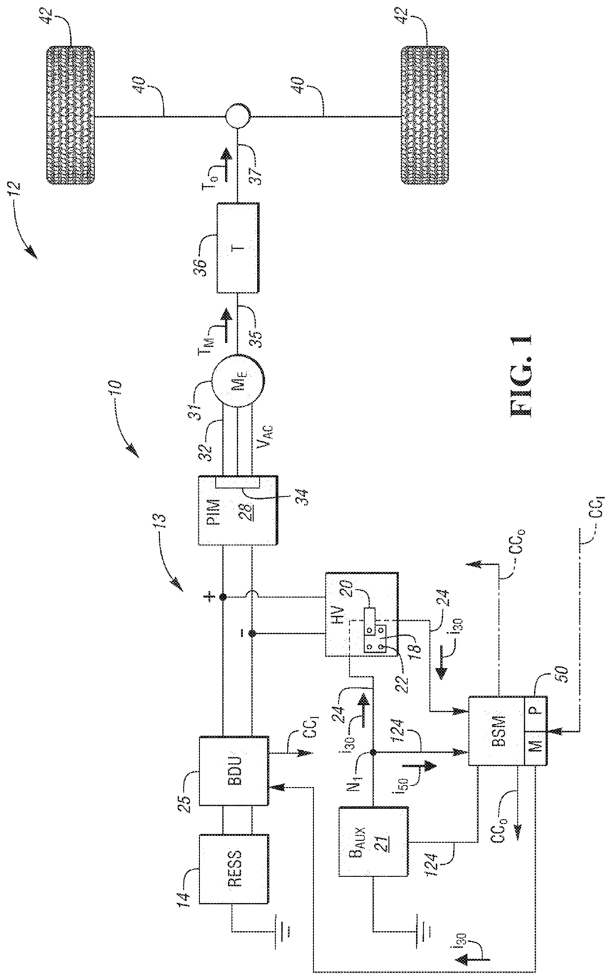
[0025]Referring to the drawings, wherein like reference numbers refer to like components, an electrical system 10 is shown in FIG. 1. The electrical system 10, which may be used as part of an example vehicle 12 as described herein or as part of a power plant or other mobile or stationary device or system, provides a high-voltage system lockout (HVSL) function that may forego use of a manual service disconnect (MSD) and / or high-voltage interlock (HVIL) process as described above.

[0026]The electrical system 10 includes multiple voltage buses, including a high-voltage (HV) bus 13 that is connected to a rechargeable energy storage system (RESS) 14. The term “high-voltage” as used herein refers to voltage levels in excess of 12-15 volt low-voltage / auxiliary voltage levels, e.g., 60-300 volts or higher. Also as used herein, the term “RESS” refers to a multi-cell rechargeable battery pack having a lithium ion, nickel metal hydride, or other application-suitable battery chemistry, as well a...


PUM


Abstract

An electrical system includes a high-voltage bus connected to a rechargeable energy storage system (RESS) and a high-voltage component connected to the RESS via the voltage bus. The component defines a service opening spanned by a removable cover. The electrical system may include a fastener connecting the cover to the component, as well as a battery disconnect unit (BDU) having a high-voltage switch device connecting the RESS to the high-voltage bus. The switch device closes responsive to a low-voltage drive current to connect the RESS to the high-voltage bus. A drive circuit conducts the current to the switch device. An electrical connector has multiple connector pieces collectively forming a switch in the drive circuit. Disconnection of the pieces from each other opens the switch to interrupt the drive current and cause the high-voltage switch device to open, which disconnects the RESS from the high-voltage bus.

Description

INTRODUCTION[0001]An electrified vehicle powertrain, power plant, or other high-voltage system may include an electrical system having separate high-voltage and low-voltage buses. While “high-voltage” and “low-voltage” are relative terms, “low-voltage” often encompasses a maximum voltage level of 12-15 volts, i.e., an auxiliary voltage, with the term “high-voltage” describing voltage levels well above auxiliary voltage levels. An electrified vehicle propulsion system, for instance, may have a maximum bus voltage of 60-300 volts, with certain emerging battery packs having a voltage capacity of 500-800 volts.[0002]Regardless of nominal voltage levels, the high-voltage and low-voltage buses of a dual-bus electrical system are respectively connected to a high-voltage rechargeable energy storage system (RESS), e.g., a lithium ion or nickel metal hydride battery pack and associated power electronics, and a lead-acid or other application-suitable auxiliary battery pack. On the high-voltage...

Claims


Application Information

Patent Timeline
Patent Type & Authority Applications(United States)
IPC IPC(8): H02J7/00B60L11/18H02P27/06H01R31/08
CPCH01R31/08H02J7/0029B60L50/51H02P27/06B60L2210/40H02J7/0063H01R13/639H01R13/42H01R13/633H01R13/7036H01M10/425B60L58/00H01M2010/4271Y02T10/72Y02T10/70Y02E60/10
Inventor FAN, YUEWANG, KONKING
Owner GM GLOBAL TECH OPERATIONS LLC
Why Eureka
Try Eureka