Wing assembly for a high endurance aircraft

Active Publication Date: 2020-02-20
HUNG LUCAS KAI LUEN
View PDF0 Cites 10 Cited by
  • Summary
  • Abstract
  • Description
  • Claims
  • Application Information

AI Technical Summary

Benefits of technology

[0011]The present invention provides devices and methods for aircrafts to

Problems solved by technology

While large unmanned aerial vehicles (UAVs) like the RQ-4 Global Hawk and the MQ-9 Reaper have exploited the endurance factor of the albatross, they lack one key trait of the bird—short takeoff and landing capabilities.
Even if the MQ-9 was scaled dow

Method used


Image

  • Wing assembly for a high endurance aircraft
  • Wing assembly for a high endurance aircraft
  • Wing assembly for a high endurance aircraft

Examples


first embodiment

of an Unmanned Aircraft

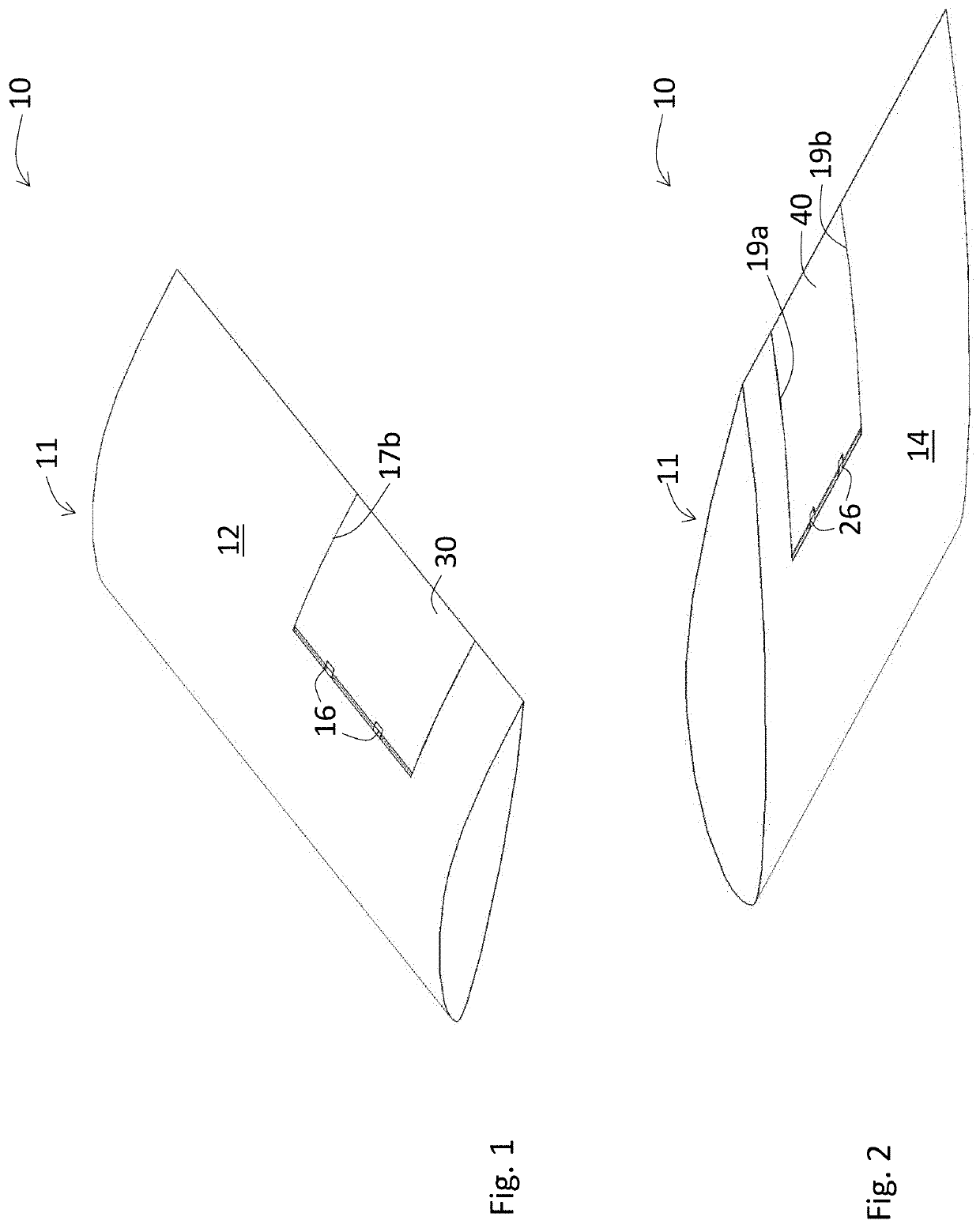
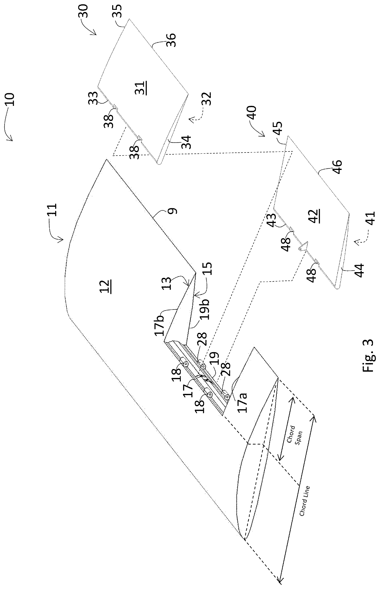
[0117]FIG. 20 shows the model unmanned aircraft 200 used for experimentation purposes, with the features of the present invention implemented on the model. This model was built using a polystyrene foam board, available for example, from Amazon as Readi-Board™ and was constructed based on design plans available from the Internet at the website Red20RC.org. In this model, the chord span of the spoiler and the flap was about two-thirds the length of the chord line of the airplane wing. The model wing was modified by removing a portion of the upper panel 216 to form a spoiler frame and a portion of the lower panel 217 to form a flap frame, and by reinforcing the front portion 215 with three 7-mm diameter carbon fiber tubes, attached inside that front portion 215, to mitigate the effects of stress that could have occurred (or may occur) at that front portion 215 during flight.

[0118]The model unmanned aircraft 200 included a receiver, a transmitter, one servo motor ...

second embodiment

of an Unmanned Aircraft

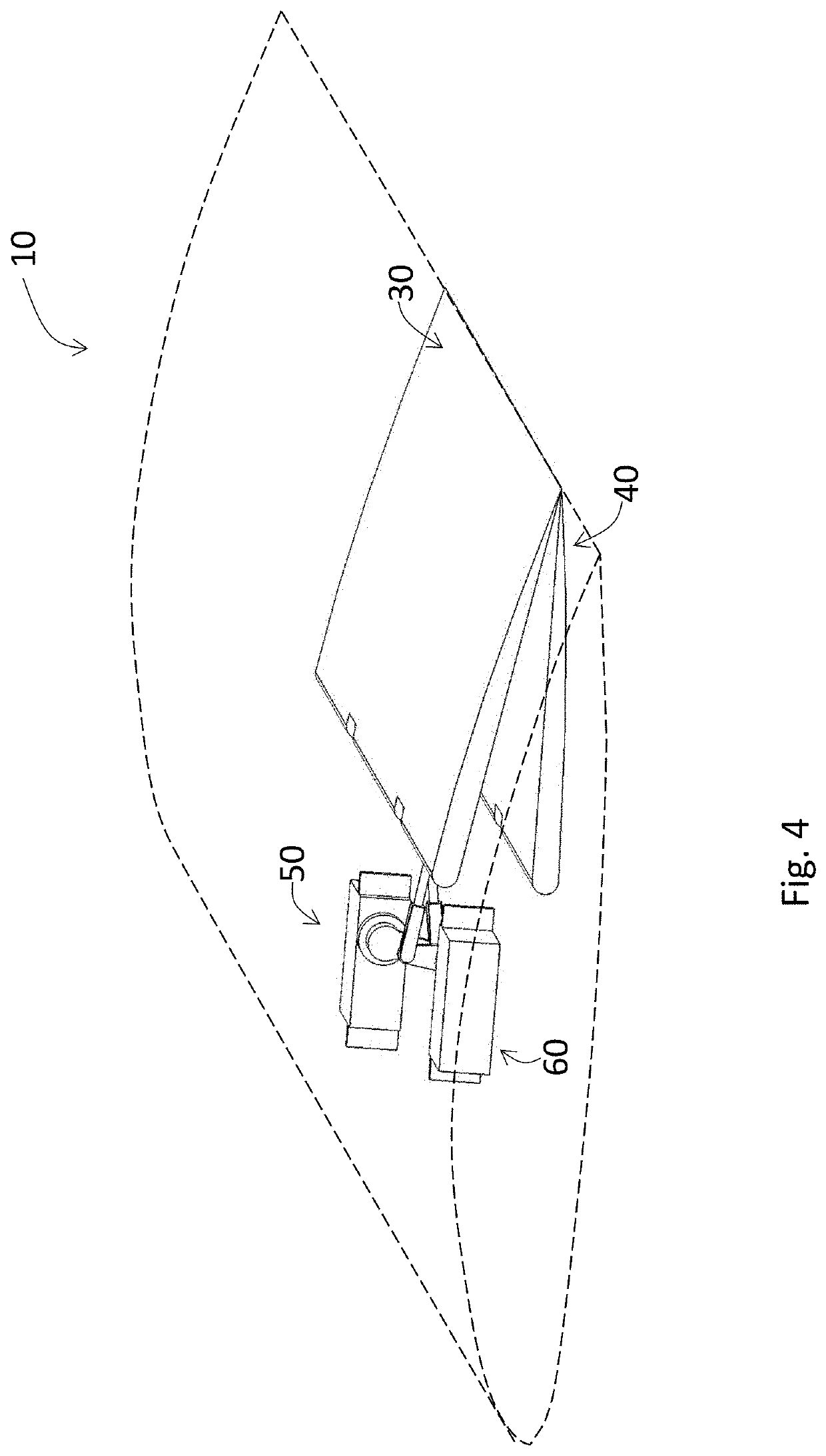
[0135]In a second embodiment, a different model aircraft shown in FIG. 24 was employed and modified as described below. The different model with the modification allowed for the aircraft to carry a flight recording device (Pixhawk 2.1) to measure real-time, in-flight parameters including velocity, acceleration, and pitch.

[0136]Aside from the metal landing gear, the fuselage and tail of the aircraft was constructed primarily out of G10 and carbon fiber composites to withstand the forces of takeoff, flight, and landing. For the wing, a combination of foam, fiberglass, and carbon fiber was used. By covering the foam wing core with fiberglass and constructing the main spar out of carbon fiber, the wing became aerodynamic, light, and robust. The spoiler and flap system of the present invention, including the spoilers and flaps, and their respective frames, occupied only 45% of the wing chord line.

[0137]In this embodiment, the control system consisted of several ind...


PUM


Abstract

An airfoil assembly comprising an airplane wing, a spoiler, and a flap for unmanned and high endurance aircraft. The spoiler is located on an upper surface of the airplane wing while the flap is located on a lower surface of the airplane wing. The spoiler and the flap can occupy at least one-third, and up to three-quarters, the chord span of the airplane wing. The spoiler and the flap are both capable of moving upwards and downwards with respect to the airplane wing through their respective frames.

Description

CROSS REFERENCE TO RELATED APPLICATIONS[0001]This application claims the benefit of U.S. Provisional Application No. 62 / 691,014 filed Jun. 28, 2018, U.S. Provisional Application No. 62 / 799,165 filed Jan. 31, 2019, and U.S. Provisional Application No. 62 / 812,764 filed Mar. 1, 2019, the disclosures of which are incorporated herein by reference in their entireties.FIELD OF THE INVENTION[0002]The present invention relates to spoilers and flaps in aircrafts.BACKGROUND OF THE INVENTION[0003]With the advent of airplanes, it has long been the goal and the trend for engineers to monitor, optimize, and improve upon established notions of flight. In the field of aeronautics, many factors come into play when it comes to solving problems prevalent in the field. These factors generally depend upon benefits associated with solving a given problem, but can also depend upon the type or purpose of an aircraft, and other economic considerations as applicable. Some improvements that have been pursued b...

Claims


Application Information

Patent Timeline
IPC IPC(8): B64C9/18B64C9/32
CPCB64C9/18B64C9/323B64C9/12B64C9/16B64C39/024B64U30/10B64U10/25
Inventor HUNG, LUCAS KAI-LUEN
Owner HUNG LUCAS KAI LUEN
Why Eureka
Try Eureka