Flow velocity distribution measuring method and particle size measuring method

a technology of flow velocity distribution and measuring method, which is applied in the direction of fluid speed measurement, liquid/fluent solid measurement, instruments, etc., can solve the problem that the flow velocity distribution inside the flow passage of an optical cell cannot be measured, and achieve the effect of accurately measuring, simple and accurate performance, and accurately measuring

Active Publication Date: 2020-02-27
NAT INST OF ADVANCED IND SCI & TECH
View PDF0 Cites 6 Cited by
  • Summary
  • Abstract
  • Description
  • Claims
  • Application Information

AI Technical Summary

Benefits of technology

[0014]Therefore, it is considered that the number density of particles is increased without decreasing the interparticle distance by decreasing the particle size. However, since the tracer particles are simply directly observed with an optical microscope observing reflective light caused from the particles by illuminated white light or their fluorescence in established PTV and PIV, the particle size cannot be decreased to or below submicron from the viewpoint of measurement sensitivity analysis.
[0028]In the invention, the flow passage may be disposed at a gap between a pair of plate shaped bodies facing in a capturing axis direction of the camera in order to decrease a thickness with respect to a horizontal width. According to the invention, a decrease in the amount of information in the thickness direction of the optical cell in the capturing axis direction of the camera can be reduced, and the flow velocity distribution measurement can be simply and accurately performed.

Problems solved by technology

However, in a flow velocity-measuring device currently available on the market, even in a case where the average flow rate of a high flow rate field or the whole system can be measured, a flow velocity distribution inside a flow passage of an optical cell cannot be measured.

Method used


Image

  • Flow velocity distribution measuring method and particle size measuring method
  • Flow velocity distribution measuring method and particle size measuring method
  • Flow velocity distribution measuring method and particle size measuring method

Examples


example

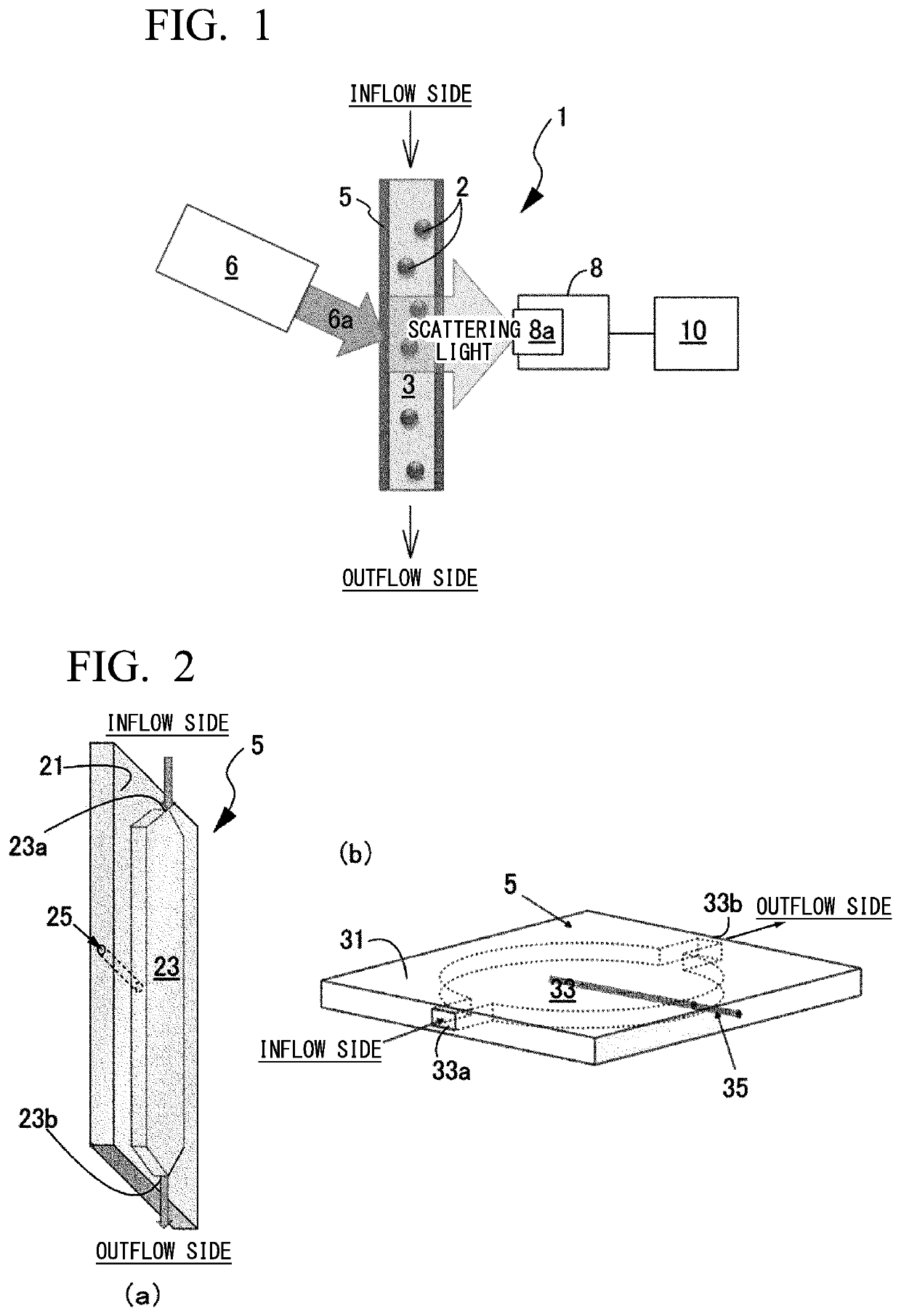
[0057]An example of observing scattering light from the particles 2 as bright spots using an optical microscope and measuring the flow velocity distribution in the measuring device 1 in FIG. 1 will be described. Polystyrene latex particles having a diameter of approximately 100 nm are used as the particles 2. Water is used as the dispersion medium 3.

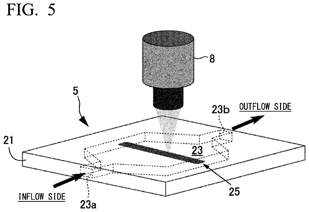
[0058]As illustrated in FIG. 5, the laser light 25 is directed to the side surface of the optical cell 5 in which the flow passage 23 having a hexagonal cylindrical shape is formed in the cell block 21. The bright spots caused by scattering light from the particles 2 dispersed in the dispersion medium 3 flowing inside the optical cell 5 are captured by the capturing unit 8. The dispersion medium 3 is directed to the flow passage 23 having a width of 16 mm and a thickness of 1 mm from the opening 23a on the inflow side and is emitted from the opening 23b on the outflow side. As a verification experiment, the flow velocity of the dispersio...


PUM

PropertyMeasurementUnit
particle sizeaaaaaaaaaa
diameteraaaaaaaaaa
thicknessaaaaaaaaaa

Abstract

A measuring method enabling simple and accurate measurement of a flow velocity distribution in a flow field inside a flow passage of an optical cell and a particle size-measuring method using the measuring method are provided. In a device including a laser light irradiation unit irradiating laser light at a wavelength λ into the flow passage, a camera capturing an inside of the flow passage to which the laser light is irradiated, and an analysis unit obtaining a flow velocity distribution in the flow field from at least a plurality of images captured in a light exposure time τ at each predetermined time interval Δt, providing a tracer particle of a smaller size than the wavelength λ of the laser light into the flow passage and capturing a bright spot attributed to the light scattering from tracer particles by the camera, and obtaining the flow velocity distribution by the analysis unit by obtaining an amount of movement of each tracer particle from movement of the bright spot and correcting a Brownian motion component from a correlation between an average value of variations of the amount of movement and Brownian motion are performed. In addition, obtaining the particle size of a measurement target particle by obtaining a corrected displacement obtained by removing a movement component of the flow field caused by the flow velocity distribution from a displacement of the measurement target particle is performed.

Description

TECHNICAL FIELD[0001]The present invention relates to a flow velocity distribution-measuring method enabling simple and accurate measurement of a flow velocity distribution in a flow field inside a flow passage of an optical cell and a particle size-measuring method using the flow velocity distribution-measuring method.BACKGROUND ART[0002]For example, as in dynamic light scattering, in the case of on-line measurement of the particle size of particles flowing in a line, the flow affects the diffusion velocity of the particles. That is, the diffusion velocity of the particles is increased, and the apparent particle size is measured to be small. Therefore, the flow velocity is to be separately measured in consideration of the effect thereof. However, in a flow velocity-measuring device currently available on the market, even in a case where the average flow rate of a high flow rate field or the whole system can be measured, a flow velocity distribution inside a flow passage of an optic...

Claims


Application Information

Patent Timeline
Patent Type & Authority Applications(United States)
IPC IPC(8): G01F1/708G01N15/02G01F1/7086
CPCG01N15/0227G01N2015/0053G01F1/7086G01P5/20G01P5/26G01F1/74G01F1/661G01F1/662G01F1/712G01N15/02
Inventor KATO, HARUHISAMATSUURA, YUSUKENAKAMURA, AYAKO
Owner NAT INST OF ADVANCED IND SCI & TECH
Why Eureka
Try Eureka