Phase-locked loop with adjustable bandwidth

a phase-locked loop and bandwidth technology, applied in the field of transceivers and receivers, can solve problems such as trade-offs, and achieve the effect of enhancing the rejection and blocking performance of adjacent channels

Active Publication Date: 2020-02-27
ANALOG DEVICES INT UNLTD
View PDF5 Cites 4 Cited by
  • Summary
  • Abstract
  • Description
  • Claims
  • Application Information

AI Technical Summary

Benefits of technology

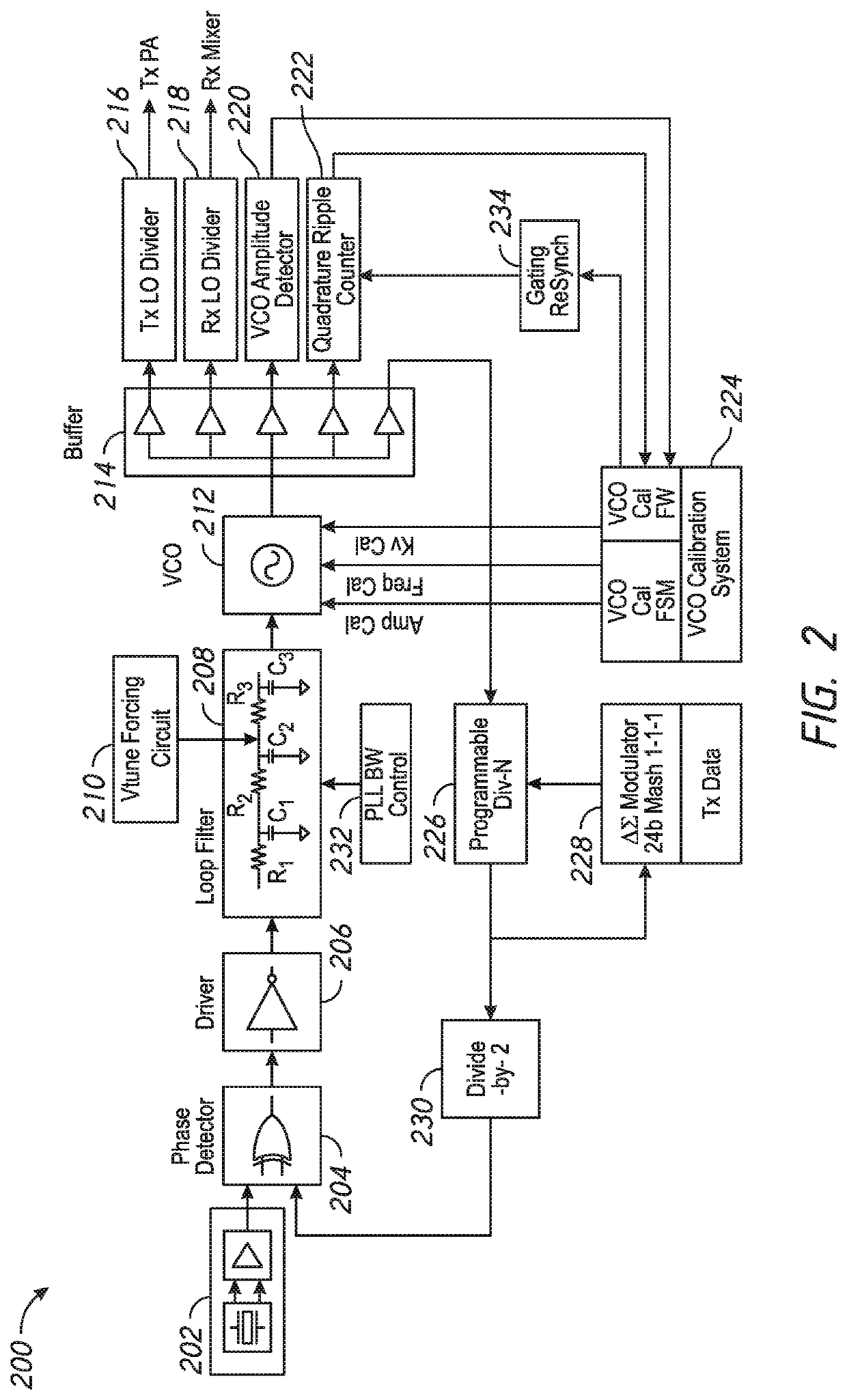
[0005]One aspect of this disclosure is a phase-locked loop having adjustable bandwidth to enhance adjacent channel rejection and blocking performance. The phase-locked loop comprises a phase detector comprising an output, a loop filter comprising an input in communication with the output of the phase detector, and a bandwidth control circuit configured to operate the loop filter in a first configuration having a first bandwidth when no interferer is detected and configured to operate the loop filter in a second configuration having a second bandwidth when an interferer is detected. The second bandwidth is greater than the first bandwidth.
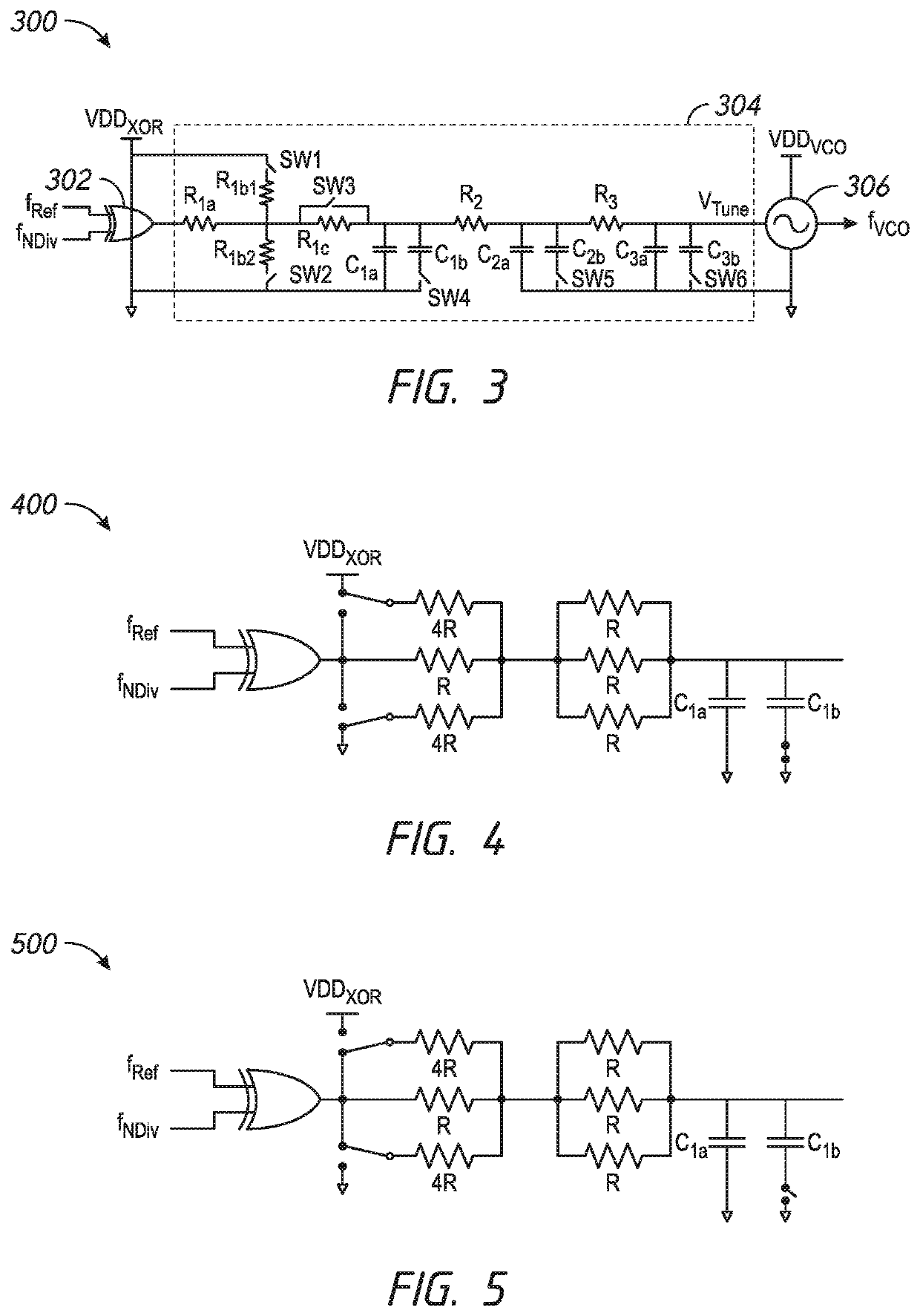
[0007]The loop filter can include at least one switch, at least one resistor and at least one capacitor, and the bandwidth control circuit can control the state of the at least one switch based at least in part on the detection of an interferer to control a configuration of the at least one resistor and the at least one capacitor in the loop filter. Operating the loop filter at the first bandwidth can enhance far-out interferer blocking resilience. Operating the loop filter at the second bandwidth can reduce close-in phase noise to enhance adjacent channel rejection.
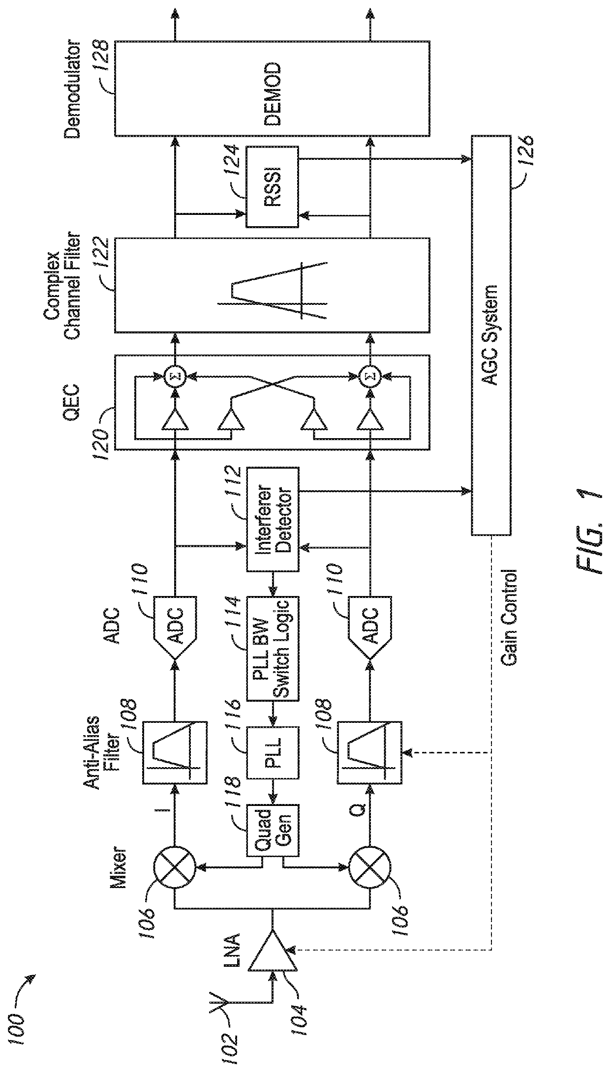
[0008]Another aspect of this disclosure is a method to adjust the bandwidth of a phase-locked loop in a receiver to enhance adjacent channel rejection and blocking performance of the receiver. The method comprises detecting an interferer in a receive signal prior to channel select filtering, and increasing a bandwidth of a phase-locked loop in a receiver in response to detecting the interferer.
[0012]Another aspect of this disclosure is a method of operating a phase-locked loop in a receiver to enhance adjacent channel rejection and blocking performance of the receiver. The method comprises operating a PLL within a receiver with a first loop bandwidth in a first operating condition in which no interferer is detected, and operating the PLL with a second loop bandwidth in a second operating condition in which an interferer is detected, the second loop bandwidth being greater than the first loop bandwidth.

Problems solved by technology

In practical designs, tradeoffs are involved.

Method used


Image

  • Phase-locked loop with adjustable bandwidth
  • Phase-locked loop with adjustable bandwidth
  • Phase-locked loop with adjustable bandwidth

Examples


Embodiment Construction

[0027]The following detailed description of certain embodiments presents various descriptions of specific embodiments. However, the innovations described herein can be embodied in a multitude of different ways, for example, as defined and covered by the claims. In this description, reference is made to the drawings where like reference numerals can indicate identical or functionally similar elements. It will be understood that elements illustrated in the figures are not necessarily drawn to scale. Moreover, it will be understood that certain embodiments can include more elements than illustrated in a drawing and / or a subset of the elements illustrated in a drawing. Further, some embodiments can incorporate any suitable combination of features from two or more drawings.

[0028]With the exponential growth of wireless traffic in congested spectrum allocations, methods to enhance the interferer resilience of low power, low cost radios is desirable. Further, low power, low cost radios are ...


PUM


Abstract

Aspects of this disclosure relate to a VLIF receiver with automatic phase noise adjustment. The presence of an interfering signal is sensed within a bandwidth around a desired channel frequency. Then the local oscillator phase noise is automatically adjusted to optimize blocking. The phase noise adjustment includes increasing the bandwidth of a phase-locked loop.

Description

CROSS-REFERENCE TO RELATED APPLICATIONS[0001]The present application claims priority to U.S. Provisional Patent Application No. 62 / 722,394, filed Aug. 24, 2018, and titled “VERY LOW INTERMEDIATE FREQUENCY (VLIF) RECEIVER WITH ADAPTIVE PHASE NOISE,” the entirety of which is hereby incorporated herein by reference.FIELD OF DISCLOSURE[0002]The disclosed technology relates to receivers and transceivers.BACKGROUND[0003]The ideal local oscillator (LO) for a down-conversion stage in a receiver would have sufficiently low phase noise at all offset frequencies to meet the required performance specifications. In practical designs, tradeoffs are involved. In a phase-locked loop (PLL), key tradeoffs are the bandwidth and the suppression of close-in voltage controlled oscillator (VCO) noise versus the peaking of quantization noise at higher offsets, such as offsets greater than the closed loop bandwidth.SUMMARY OF THE DISCLOSURE[0004]The innovations described in the claims each have several aspe...

Claims


Application Information

Patent Timeline
Patent Type & Authority Applications(United States)
IPC IPC(8): H03G3/34H03L7/107H03L7/093H03L7/095H03F3/181
CPCH03L7/1072H03L7/095H03G3/344H03F3/181H03L7/093H03G3/3052H03L7/107H03L7/104H03L7/1974
Inventor KEARNEY, NIALL KEVIN
Owner ANALOG DEVICES INT UNLTD
Why Eureka
Try Eureka