Adaptive illumination apparatus, method, and applications

a technology of adaptive illumination and apparatus, applied in the field of smart laser sources, can solve the problems of poor deflection efficiency of aod, difficult differentiation, and high cost of optical setup for ramps

Active Publication Date: 2020-03-05
CORNELL UNIVERSITY
View PDF0 Cites 1 Cited by
  • Summary
  • Abstract
  • Description
  • Claims
  • Application Information

AI Technical Summary

Benefits of technology

The present invention is about methods for adaptive illumination in imaging systems. The invention involves generating a high-resolution structural image of a sample, processing it to identify regions of interest, and converting them into a data sequence to modulate an excitation source. The resulting pulse intensity pattern is then amplified, shifted to a second wavelength, and transmitted to a laser scanning microscope for imaging. The technical effects of the invention include improved imaging of samples at high resolution, improved signal-to-noise ratios, and improved optical sectioning capabilities.

Problems solved by technology

As the brain is estimated to have billions of neurons, which are dense and difficult to differentiate.
The field-of-view of RAMP is small and typically less than 200 μm in X, Y and Z. The optical setup for RAMP is expensive and complex, requiring four large-aperture AODs and four relay telescopes for the scanning system.
The deflection efficiency of the AOD is poor, typically less than 70% for each AOD at approximately 800 nm.
At the long wavelength windows of 1300 nm and 1700 nm, the efficiency of AOD is much worse due to material limitations.
Due to these difficulties, RAMPs have only seen limited deployment in neuroscience research, and all RAMPs were performed at a wavelength less than 1.06 μm.

Method used


Image

  • Adaptive illumination apparatus, method, and applications
  • Adaptive illumination apparatus, method, and applications
  • Adaptive illumination apparatus, method, and applications

Examples


Embodiment Construction

[0032]The present disclosure is directed to embodiments of a method and system for adaptive illumination.

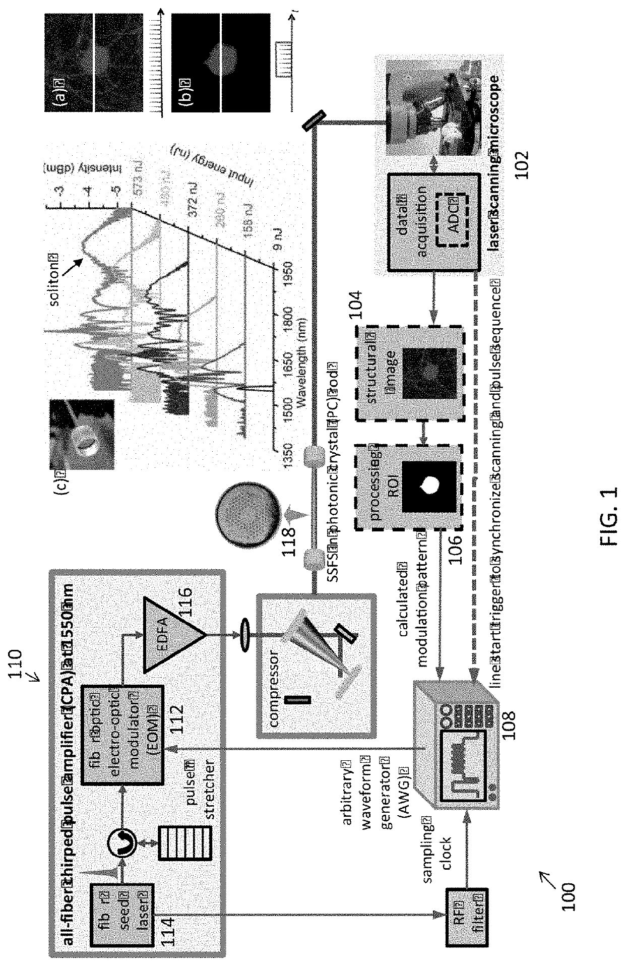
[0033]According to one embodiment, the disclosure is directed to an imaging system for adaptive illumination. Referring first to FIG. 1, there is shown a schematic representation of an imaging system 100 for adaptive illumination, in accordance with an embodiment. The system 100 comprises a laser scanning microscope 102 for raster scanning of a sample. Raster scanning of the sample produces a high-resolution structural image 104. Image processing is then performed on the high-resolution structural image 104 to determine regions of interest (ROIs) 106. For recording the activity of neurons, the ROIs 106 are defined by the regions of the somas of the neurons. After determining the ROIs 106, the ROI 106 information is converted to a digital sequence, a calculated modulation pattern. The calculated modulation pattern is then used to control an arbitrary waveform generator (AWG) 108, ...


PUM


Abstract

A system and method for adaptive illumination, the imaging system comprising an excitation source having a modulator, which generates a pulse intensity pattern having a first wavelength when the excitation source receives a modulation pattern. The modulation pattern is a data sequence of a structural image of a sample. An amplifier of the imaging system is configured to receive and amplify the pulse intensity pattern from the modulator. A frequency shift mechanism of the imaging system shifts the first wavelength of the pulse intensity pattern to a second wavelength. A laser scanning microscope of the imaging system receives the pulse intensity pattern having the second wavelength.

Description

CROSS-REFERENCE TO RELATED APPLICATIONS[0001]This application claims priority to pending U.S. Provisional Patent Application No. 62 / 422,268, filed Nov. 15, 2016 and entitled “Adaptive Illumination Apparatus, Method, and Applications,” the entirety of which is hereby incorporated by reference.FIELD OF THE INVENTION[0002]The present disclosure is directed generally to a smart laser source, and more particularly to a system and method for adaptive illumination based on the sample under study.BACKGROUND[0003]In the field of neuroscience, the detection and understanding of neural activity is critical in diagnosing diseases and other disorders and researching treatments or cures to such diseases and disorders. For example, studying rhythmic patterns of neural activity, neural oscillations, can be used to diagnose tremors, such as those indicating Parkinson's disease, migraines, and epilepsy. When new treatments are developed and tested, neural activity can be studied to determine if the p...

Claims


Application Information

Patent Timeline
IPC IPC(8): A61B5/00H01S3/067
CPCG01N2201/0697H01S3/06754A61B5/40A61B5/0071A61B5/00A61B5/0075A61B2562/0233G02B21/0032G02B21/0076G02B21/361G02B2207/114
InventorXU, CHRISCHARAN, KRITILI, BOBUTTOLPH, MICHAEL
OwnerCORNELL UNIVERSITY