
Graphenic fibers, yarns, composites, and methods of making the same

a graphene fiber and composite technology, applied in the field of graphene fibers, yarns, composites, and methods of making the same, can solve the problems of little overall benefit, and achieve the effects of less brittleness, lower densities, and higher failure strain

Pending Publication Date: 2020-03-05
CORNELL UNIVERSITY
View PDF10 Cites 17 Cited by
  • Summary
  • Abstract
  • Description
  • Claims
  • Application Information

AI Technical Summary

Benefits of technology

The patent describes a method for producing strong and lightweight graphenic fibers that can replace carbon fibers in industries such as aerospace and automobile. The method involves heating a liquid containing a graphenic component and a polymer to form fibers. The resulting fibers have high strength and low density, making them ideal for use in these industries. The method also allows for the formation of multi-layered fibers that provide better alignment and performance. The use of a polymer helps to form fine fibers, which further improves the strength and performance of the fibers. Overall, the method provides a way to produce high-quality, lightweight graphenic fibers that can replace carbon fibers in various applications.

Problems solved by technology

Some preliminary attempts to manufacture graphene fibers produced fibers with low densities, but also with low tensile strengths (e.g., 0.1-0.5 GPa), relative to carbon fibers (e.g., 2-7 GPa), providing little overall benefit in those applications where high strength and low mass is desired because in order to achieve a comparable strength benefit as carbon fiber, more volume and a comparable mass of graphene fiber would be required.

Method used


Image

  • Graphenic fibers, yarns, composites, and methods of making the same
  • Graphenic fibers, yarns, composites, and methods of making the same
  • Graphenic fibers, yarns, composites, and methods of making the same

Examples


example 1

uid Stock

[0128]A first stock fraction is prepared by charging graphene oxide (0.75 wt. %), the graphenic component, into an aqueous medium. The suspension is stirred until homogeneous. A second fraction stock is prepared by charging polyvinyl alcohol (PVA) into an aqueous medium (de-ionized water) (0.1 g polymer / mL medium). The mixture is stirred until homogenous (dissolved).

[0129]The fluid stock having a GO:PVA weight ratio of 1:10 is prepared by combining the first and second stock fractions in the appropriate amounts and stirring until homogenous.

[0130]Additional fluid stocks are prepared as described above, with GO:PVA weight ratios of 1:5, 1:3, and 1:2.

example 2

inning GO / PVA

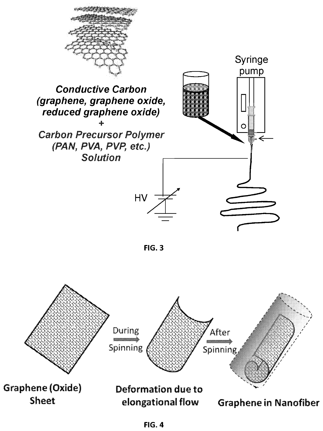
[0131]The fluid stock of Example 1 is electrospun by a gas-assisted technique. The overall process and apparatus is depicted in FIG. 1. The fluid stock is loaded into a syringe pump connected to a spinneret with an inner nozzle diameter (fluid stock) of 4.13×10⁻⁴ m and an outer (air) diameter of 1.194×10⁻³ m. The distance between the nozzle and the collector is about 15-20 cm and the fluid stock is spun at a rate of about 0.1-0.5 ml / min. A charge of about +15-25 kV is maintained at the collector. The air velocity at the nozzle is >5 m / s. The temperature of the air and fluid stock at the nozzle is about 300 K.

example 3

rns (Rotating Collector)

[0132]The (grounded) collector of Example 2 is in the shape of a cone, with the open end facing the electrospinning nozzle. A pair of nozzles are located on opposite sides of the collector, as illustrated in the FIG. 9. As the fluid stock is electrospun, a fibrous web or mat forms on and in proximity to the collector. As the collector rotates, the fibrous web twists to form a twisted yarn, which is drawn and collected on a spool, such as illustrated in FIG. 9.


PUM

PropertyMeasurementUnit
average lengthaaaaaaaaaa
lengthaaaaaaaaaa
widthaaaaaaaaaa

Abstract

Provided in certain embodiments are high performance graphene fibers and yarns, including components and precursors thereof, and composites comprising the same. Also provided herein are methods of manufacturing such fibers, yarns, composites, and components / precursors thereof.

Description

CROSS REFERENCE TO RELATED APPLICATIONS[0001]This application claims priority to U.S. Provisional Application No. 62 / 506,956, filed on May 16, 2017, the disclosure of which is hereby incorporated by reference.BACKGROUND OF THE INVENTION[0002]The demand for carbon fibers has been increasing steadily, and is expected to reach 89,000 ton by 2020. The largest application for carbon fibers is the aerospace and defense industry, which takes up 30% of global demand and 50% of global revenues in carbon fibers. Carbon fibers are generally produced by stabilizing polymer (PAN) fibers at a temperature less than 400° C., carbonizing the polymer (PAN) fibers at about 1500° C., and optional graphitization of the fibers at a temperature up to 3000° C.[0003]Carbon fibers can exhibit up to six times the specific strength and 67% greater relative stiffness than steel. Specifically, in typical carbon fibers, the tensile strength of the fiber is very high, at about 2-7 GPa. The density / mass of the carb...

Claims


Application Information

Patent Timeline
Patent Type & Authority Applications(United States)
IPC IPC(8): C04B35/622D01D5/00C01B32/16C04B35/83
CPCC04B2235/5264C04B2235/96C04B2235/5248D01D5/0046C01B32/16C04B2235/526C04B35/83C04B35/62277C01B32/184D01D5/0076D01F1/02D01F9/14C04B35/62272C04B35/80
Inventor JOO, YONG LAKFEI, LINGKIM, SEUNG WAN
Owner CORNELL UNIVERSITY
Learn More