Optical interfaces and methods for rapid volumetric neural modulation and sensing

a volumetric neural and optical interface technology, applied in the field of imaging technologies, can solve the problems of limiting specificity, limiting light penetration, and failing to record the ability to be detected

Inactive Publication Date: 2020-03-05
UNIV OF COLORADO THE REGENTS OF
View PDF2 Cites 5 Cited by
  • Summary
  • Abstract
  • Description
  • Claims
  • Application Information

AI Technical Summary

Problems solved by technology

For example, the electrodes are situated at a fixed location within tissue and elicit an undesirably robust neuroinflammatory response, recording capability fails over time, and electrical stimulation by microelectrode arrays indiscriminately affects all local neurons and axons of passage.
However, light penetration is limited by light scattering and awake-behaving imaging systems utilize wide-field light for optogenetic stimulation, limiting specificity.
Scaling this technology, however, suffers from brain-tissue response to electrode insertion resulting in progressive degradation of neuronal signal.
An additional problem is that massive signal processing of spikes recorded by electrodes is challenging because spike classification methods typically rely on manual or semi-automatic processing.
Alternative approaches that place electrodes on the surface involve less tissue displacement, and are more biocompatible.
However, while single neuron activity can be sparsely sampled from the cortical surface, the range and specificity of surface recording and stimulation is currently limited.
Therefore, scaling of multielectrode array recording to sample large neural populations is problematic.
In addition, the spatial relationships between neurons in a population are more difficult to discern.
A major challenge in optical imaging is the ability to record from deep light-scattering brain tissue.
However, this high power requirement complicates implementation, for example, such that wireless implementation is not practical.
Moreover, the head-fixed setup typically required in such systems undesirably constrains the behavior of the animal or subject, and a tethered implementation has small field of view.
Head-mounted and fiber-coupled microscopes typically have a limited imaging depth, and as they are typically designed for widefield illumination, they suffer from a lack of spatial precision for stimulation.
Thus, current imaging technologies have multiple limitations that curtail effectiveness.
Most imaging systems either constrain natural movement and behavior (through head-fixation), do not allow for simultaneous high-resolution functional imaging with spatially-localized neuromodulation, and / or are restrained to single, small field of view (FOV).

Method used


Image

  • Optical interfaces and methods for rapid volumetric neural modulation and sensing
  • Optical interfaces and methods for rapid volumetric neural modulation and sensing
  • Optical interfaces and methods for rapid volumetric neural modulation and sensing

Examples


Embodiment Construction

[0033]To address challenges in the art such as those described above in the Technical Background section, the present disclosure provides a variety of methods and systems for rapid modulation and sensing of tissue, e.g., neural tissue such as brain tissue.

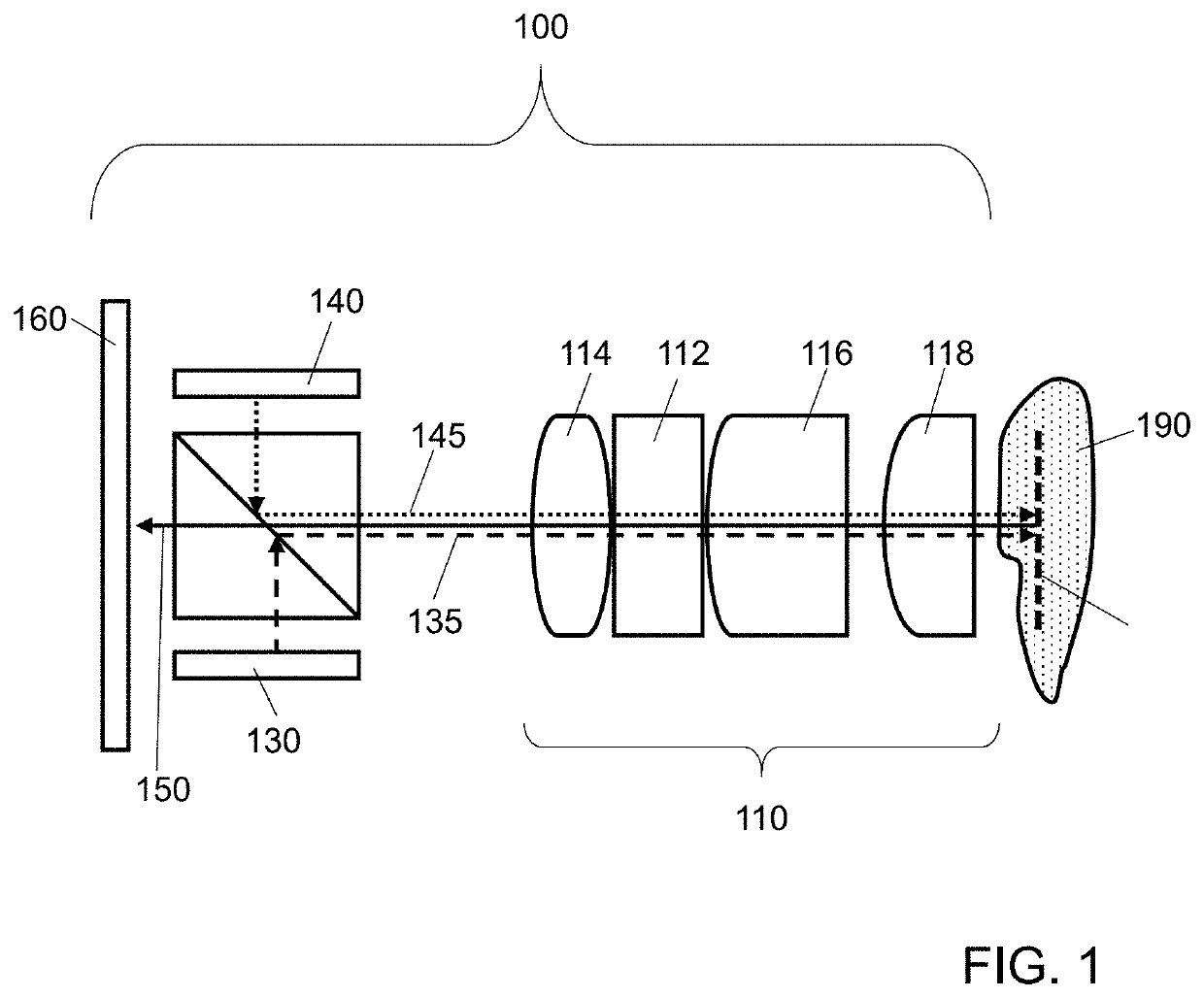
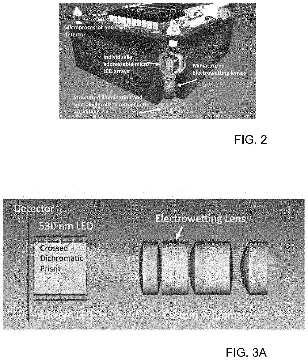
[0034]For example, various embodiments of the present disclosure provide for a miniature microscope system and methods for using it for stimulating and imaging neural activity using light. The closest technology would be the miniscope, (e.g., a miniature wide field fluorescent microscope that incorporates an LED light source with optics, dichroics, and a miniature CMOS detector). Some of the differences of the present technology include the following:

[0035]1. Some embodiments include a miniature electrowetting electrically tunable lens that scans the focal length of the microscope to allow three-dimensional imaging. Electrowetting electrically tunable lenses are described in more detail, e.g, in U.S. Patent Application Publication ...


PUM


Abstract

The present disclosure provides methods and systems for modulation and imaging of tissue. Various embodiments relate to optical interfaces and methods for rapid volumetric neural sensing and modulation, using structured illumination and

Description

CROSS-REFERENCE TO RELATED APPLICATIONS[0001]This application claims the benefit of priority of U.S. Provisional Patent Application No. 62 / 724,793, filed Aug. 30, 2018, which is hereby incorporated herein by reference (including all appendices) in its entirety for all purposes.STATEMENT REGARDING FEDERALLY SPONSORED RESEARCH OR DEVELOPMENT[0002]This invention was made with government support under grant number EY029458 awarded by the National Institutes of Health. The government has certain rights in the invention.BACKGROUND OF THE DISCLOSURE1. Field[0003]Various embodiments of the present technology generally relate to imaging technologies. More specifically, various embodiments of the present technology relate to optical interfaces and methods for rapid volumetric neural sensing and modulation.2. Technical Background[0004]Optical imaging of neural populations allows for simultaneous high-fidelity measurements of spatial and temporal dynamics of functional activity. Through combina...

Claims


Application Information

Patent Timeline
Patent Type & Authority Applications(United States)
IPC IPC(8): G02B21/00G02B27/02
CPCG02B21/0036G02B21/006G02B27/02G02B21/0032G02B21/0076G02B21/082G02B21/02G02B21/367G02B26/005G02B2207/115G01N21/6458G01N2201/0635
Inventor GIBSON, EMILY A.WELLE, CRISTINRESTREPO, DIEGOSHEPHERD, DOUGLASGOPINATH, JULIET T.BRIGHT, VICTOR M.CORMACK, ROBERT H.KYMISSIS, LOANNIS
Owner UNIV OF COLORADO THE REGENTS OF
Why Eureka
Try Eureka