System for Determining Excitation Frequency of Vibratory Stress Relief and Method therefor

Active Publication Date: 2020-03-12
SHANGHAI MARITIME UNIVERSITY
View PDF0 Cites 5 Cited by
  • Summary
  • Abstract
  • Description
  • Claims
  • Application Information

AI Technical Summary

Benefits of technology

The present invention proposes a new method for determining the excitation frequency of vibratory stress relief treatment for components. This method takes into account the residual stress distribution state on the surface of the component, which helps to improve the vibration effect and eliminate the residual stress. The proposed method uses the maximum difference of voltage peak as the excitation frequency, which implies that the micro-defects of the component are most susceptible to change under the action of such an excitation frequency. The excitation frequency determining method is more efficient and reduces the processing workload of the host computer system. Overall, the present invention reduces the workload and improves the operating efficiency of the entire vibratory stress relief system.

Problems solved by technology

The excitation frequency of vibratory stress relief determined by such a sweeping frequency method is not conducive to achieving an ideal effect of vibratory stress relief on eliminating residual stress.
How to select a suitable excitation frequency of vibratory stress relief from the multiple frequencies has become an urgent problem to be solved in the research field of vibratory stress relief process parameters.
In particular, the energy available at each frequency point is very limited when the number of frequencies employed is to synthesize the excitation signal.
In this case, the effect of the multi-frequency coupled vibratory stress relief treatment on the component is not very satisfactory.
Although adjusting the output energy of the exciter may increase the multi-frequency coupled vibration energy, change from such adjustment is ultimately limited, resulting in less energy at each frequency point.

Method used


Image

  • System for Determining Excitation Frequency of Vibratory Stress Relief and Method therefor
  • System for Determining Excitation Frequency of Vibratory Stress Relief and Method therefor

Examples


Embodiment Construction

[0028]The present invention will be further described with reference to the accompanying drawings:

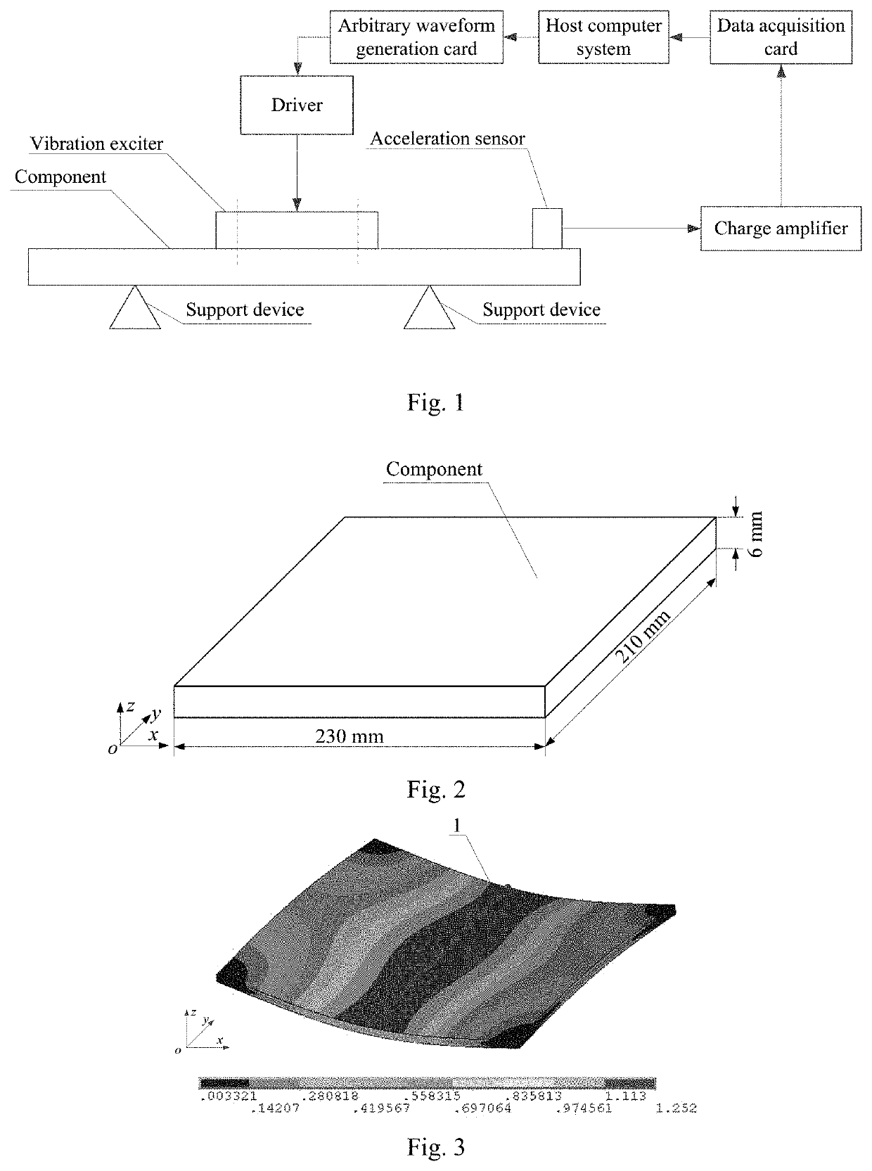
[0029]The system for determining the excitation frequency of vibratory stress relief comprises a host computer system, an arbitrary waveform generation card, a driver, a vibration exciter, an acceleration sensor, a charge amplifier, a data acquisition card, and a support device. The vibration exciter is mounted on the surface of the component, and the component is supported by the elastic support device; the excitation signal outputted by the arbitrary waveform generation card controlled by the host computer system is input to the vibration exciter via the driver, thereby driving the vibration exciter to generate vibration; the acceleration sensor is mounted on the component, the acceleration sensor is connected to the input port of the charge amplifier, the output port of the charge amplifier is connected to the input port of the data acquisition card, and the output port of the data a...


PUM

PropertyMeasurementUnit
Fractionaaaaaaaaaa
Timeaaaaaaaaaa
Electric potential / voltageaaaaaaaaaa

Abstract

A system for determining the excitation frequency of vibratory stress relief is disclosed, comprising a host computer system, an arbitrary waveform generation card, a driver, a vibration exciter, an acceleration sensor, a charge amplifier, a data acquisition card, and a support device. The vibration exciter is mounted on the surface of a component, and the component is supported by the elastic support device; the host computer system comprises a finite element numerical simulation module, a preferred excitation frequency determination module, a reference voltage peak setting module, an excitation signal synthesis module, a voltage signal acquisition module, a Fourier transform module, an actual voltage peak acquisition module, and a voltage peak difference storage module. The method for determining the vibratory stress relief frequency comprises the following steps: numerical simulating; determining the preferred excitation frequency; synthesizing the excitation signal; Fourier transforming; determining the excitation frequency for the vibratory stress relief treatment from the preferred excitation frequency. The present invention is advantageous in that it is capable of determining the vibratory stress relief excitation frequency based on the surface residual stress distribution state of the component.

Description

[0001]The present application claims priority benefit of CN 109321743A, filed on Sep. 10, 2018, the entirety of which being incorporated by reference herein.FIELD OF INVENTION[0002]The present invention relates to the field of vibratory stress relief technology, and relates in particular to a system for determining the excitation frequency of vibratory stress relief and a method therefor.BACKGROUND ART[0003]Elimination of residual stress of components induced by manufacturing processes is an important topic in the field of mechanical manufacturing industry. Vibratory stress relief technology has the characteristics of good processing effect, short processing time, less environmental pollution, low energy consumption and easiness to perform operation on site. It is a high efficiency, energy-saving and environmental protection stress relief technology. Therefore, research on vibratory stress relief technology has important engineering application value. At present, the widely used vib...

Claims


Application Information

Patent Timeline
IPC IPC(8): G01N29/46G01N29/44G01N29/12
CPCG01N2291/263G01N29/12G01N29/46G01N2291/014G01N29/4472C21D10/00G06F30/00G01N29/348Y02P10/20G05B13/04
Inventor GU, BANGPINGWANG, SIQIYAN, ZHENWUWEI, WEIHU, XIONGLAI, JINTAO
Owner SHANGHAI MARITIME UNIVERSITY
Why Eureka
Try Eureka