
Mdof micro-lubrication intelligent spray head system for CNC milling machine

Pending Publication Date: 2020-03-19
QINGDAO TECHNOLOGICAL UNIVERSITY +1
View PDF0 Cites 4 Cited by
  • Summary
  • Abstract
  • Description
  • Claims
  • Application Information

AI Technical Summary

Benefits of technology

The device combines the use of a stepping motor and air pressure to provide power for the rotating disk and telescopic cylinder. It also has an infrared sensor to collect machining data in real time, which is used to adjust the angle of the spray head for optimal machining. The device solves issues with traditional cutting fluid spray heads by allowing for adjustable angles and eliminating dead corners on the cut surface. Additionally, it reduces waste of cutting fluid.

Problems solved by technology

The cooling and lubricating mode has a low utilization rate and increases huge machining and production costs.
Moreover, the scrapped coolant may cause great damage to the environment if not handled properly.
However, the dry machining technology does not solve the problem of cooling of the cutting region, and causes surface burning, deterioration of surface integrity and other problems of workpieces.
Although many designers have designed micro-lubrication systems, many problems still exist in practical application.
Before milling with a milling machine, people may approximately align the spray head with a milling cutter by understanding the milling processing, however, when the milling machine mills a circumference, a deep groove and other abnormal angles, the cutting fluid cannot be sprayed around a working point of the milling cutter, causing waste of the cutting fluid and surface burning of the workpieces; and continuous tracking and spraying of the cutting fluid for machining with the milling machine also cannot be realized.

Method used


Image

  • Mdof micro-lubrication intelligent spray head system for CNC milling machine
  • Mdof micro-lubrication intelligent spray head system for CNC milling machine
  • Mdof micro-lubrication intelligent spray head system for CNC milling machine

Examples


Embodiment Construction

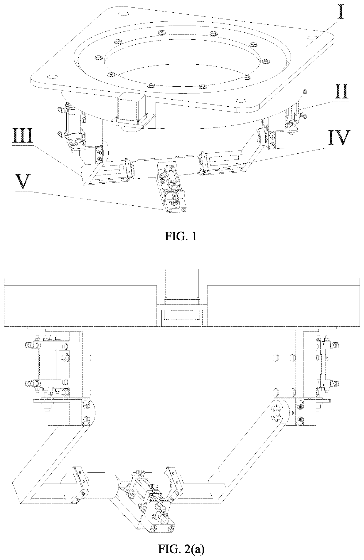
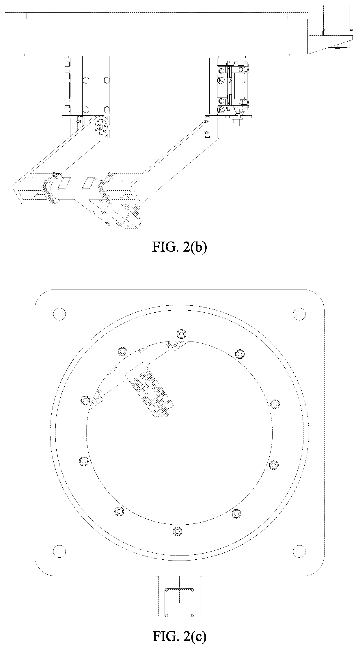
[0057]FIG. 1 is an isometric view of an MDOF micro-lubrication intelligent spray head system for a CNC milling machine. FIG. 2 shows three views of the MDOF micro-lubrication intelligent spray head system for the CNC milling machine. FIG. 2(a) is a front view, FIG. 2(b) is a left view, and FIG. 2(c) is a top view.

[0058]As shown in FIG. 1 and FIGS. 2(a)-(c), the MDOF micro-lubrication intelligent spray head system provided by the present invention comprises the following five parts: an annular rotating platform I, a longitudinal telescopic arm II, a rotating arm III, a spray head mounting platform IV and an information acquisition system V.

[0059]The annular rotating platform comprises a rotating piece which rotates along a horizontal circumferential direction. A bottom of the rotating piece is connected with at least one longitudinal telescopic arm; a lower end of the longitudinal telescopic arm is connected with the rotating arm; the rotating arm rotates within a set angle range by ...


PUM

PropertyMeasurementUnit
Lengthaaaaaaaaaa
Lengthaaaaaaaaaa
Lengthaaaaaaaaaa

Abstract

The present invention discloses an MDOF (multi-degree-of-freedom) micro-lubrication intelligent spray head system for a CNC milling machine, comprising an annular rotating platform, a longitudinal telescopic part, a rotating part, an intelligent spray head mounting platform and an information acquisition system. The annular rotating platform comprises a rotating piece which rotates along a horizontal circumferential direction; a bottom of the rotating piece is connected with at least one longitudinal telescopic part; a lower end of the longitudinal telescopic part is connected with the rotating part; the rotating part rotates within a set angle range by taking a point connected with the longitudinal telescopic part as an axis; the intelligent spray head mounting platform is connected with the rotating part and moves along with the rotating part; and the information acquisition system is mounted on the intelligent spray head mounting platform.

Description

CROSS-REFERENCE TO RELATED APPLICATIONS[0001]This application is a continuation of International Patent Application No. PCT / CN2018 / 119446 with a filing date of Dec. 6, 2018, designating the United States, now pending, and further claims priority to Chinese Patent Application No. 201810707515.3 with a filing date of Jul. 2, 2018. The content of the aforementioned applications, including any intervening amendments thereto, are incorporated herein by reference.TECHNICAL FIELD[0002]The present invention belongs to the field of metal processing, and particularly relates to an MDOF (multi-degree-of-freedom) micro-lubrication intelligent spray head system for assisting a CNC milling machine.BACKGROUND OF THE PRESENT INVENTION[0003]A machining region is cooled and lubricated by a large amount of emulsion, cutting oil, coolant and the like in traditional machining. The cooling and lubricating mode has a low utilization rate and increases huge machining and production costs. Moreover, the scr...

Claims


Application Information

Patent Timeline
IPC IPC(8): B23Q11/12B05B3/02
CPCB23Q11/122B05B3/025B23Q11/10B23Q11/1038B23Q11/1046B23Q11/1076B23Q1/5418B05B13/0431Y02P70/10B05B15/65B05B15/652B05B15/68B23B27/10B23Q11/1084B23Q16/04B23Q2705/104B23Q2735/002Y10S29/054
Inventor LI, CHANGHESUI, MENGHUAWU, WENTAOZHANG, NAIQINGWU, QIDONGLI, JUNHAN, ZHIGUANGJI, HEJUGAO, TENGZHANG, YANBINYANG, MINJIA, DONGZHOUYIN, QINGANZHANG, XIAOYANGHOU, YALI
Owner QINGDAO TECHNOLOGICAL UNIVERSITY
Learn More