Automated waste water recycling system using advanced electro-coagulation unit

Active Publication Date: 2020-03-26
GREEN TECHNO CORP +1
View PDF0 Cites 2 Cited by
  • Summary
  • Abstract
  • Description
  • Claims
  • Application Information

AI Technical Summary

Benefits of technology

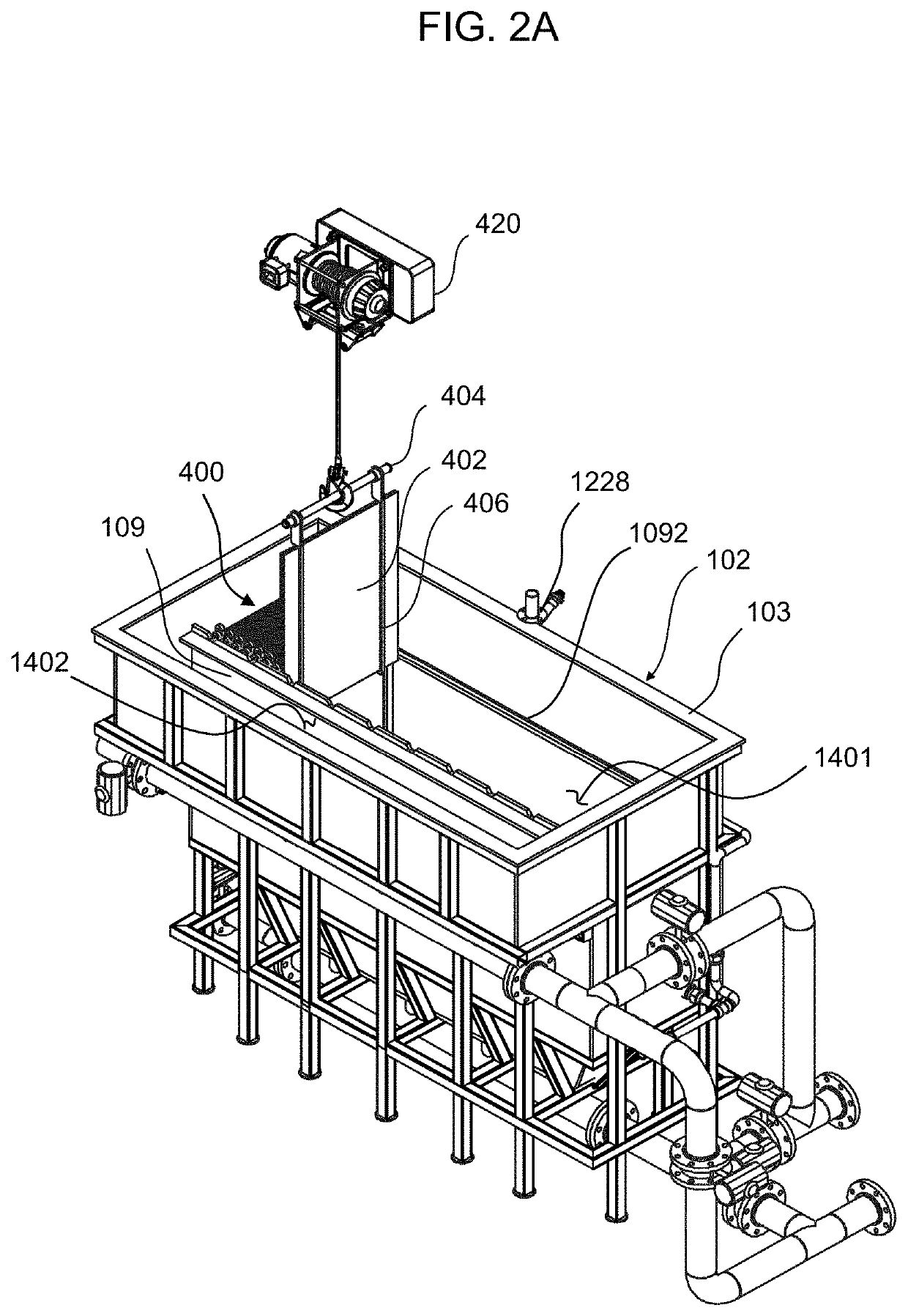
[0013]The advantages of the present invention are: (1) improvement of the efficiency of waste water treatment where the automated waste water treatment system produces a 97% recovery of pure reusable water from waste water; (2) increase the convenience of maintaining the electrodes through the use of electrode holders constructed on a top edge of the electrode where a hoist can remove the electrode from the electrocoagulation unit for maintenance, repair, or replacement; (3) increased longevity of the electrodes used in the electrocoagulation of waste water through removal of solids trapped on the surface of the electrodes by employing an air filter grid to physically agitate the solids that adhere to the electrodes and an acid wash, the latter involving the charging of an acid solution, wherein the acid that is spent can be advantageously utilized, into the waste water to be treated—the ferrous chloride in the spent solution reacts to form the hydroxides (hydroxides being coagulating agents that coagulate/coalesce colloidal suspensions and emulsions) wherein the formation of hydroxide commences in the collection tank and continues in the EC unit such that this automated system provides another novel utilization of an inconvenie

Problems solved by technology

Even so, such techniques have their drawbacks as they are prone to be time consuming, inconvenient, and relatively inefficient while requiring large environmental footprints.
Generally, methods and apparatus employing such techniques cannot economically treat wastewater as quickly and efficiently as it is generated in a large scale industrial process so as to satisfactorily r

Method used


Image

  • Automated waste water recycling system using advanced electro-coagulation unit
  • Automated waste water recycling system using advanced electro-coagulation unit
  • Automated waste water recycling system using advanced electro-coagulation unit

Examples


Embodiment Construction

[0024]Reference will now be made in detail to the preferred embodiments of the present invention, examples of which are illustrated in the accompanying drawings, which form a part of this disclosure. It is to be understood that this invention is not limited to the specific devices, methods, conditions or parameters described and / or shown herein, and that the terminology used herein is for the purpose of describing particular embodiments by way of example only and is not intended to be limiting of the claimed invention.

[0025]Also, as used in the specification including the appended claims, the singular forms “a”, “an”, and “the” include the plural, and reference to a particular numerical value includes at least that particular value, unless the context clearly dictates otherwise. Ranges may be expressed herein as from “about” or “approximately” one particular value and / or to “about” or “approximately” another particular value. When such a range is expressed, another embodiment includ...


PUM

PropertyMeasurementUnit
Heightaaaaaaaaaa
Gravityaaaaaaaaaa
Timeaaaaaaaaaa

Abstract

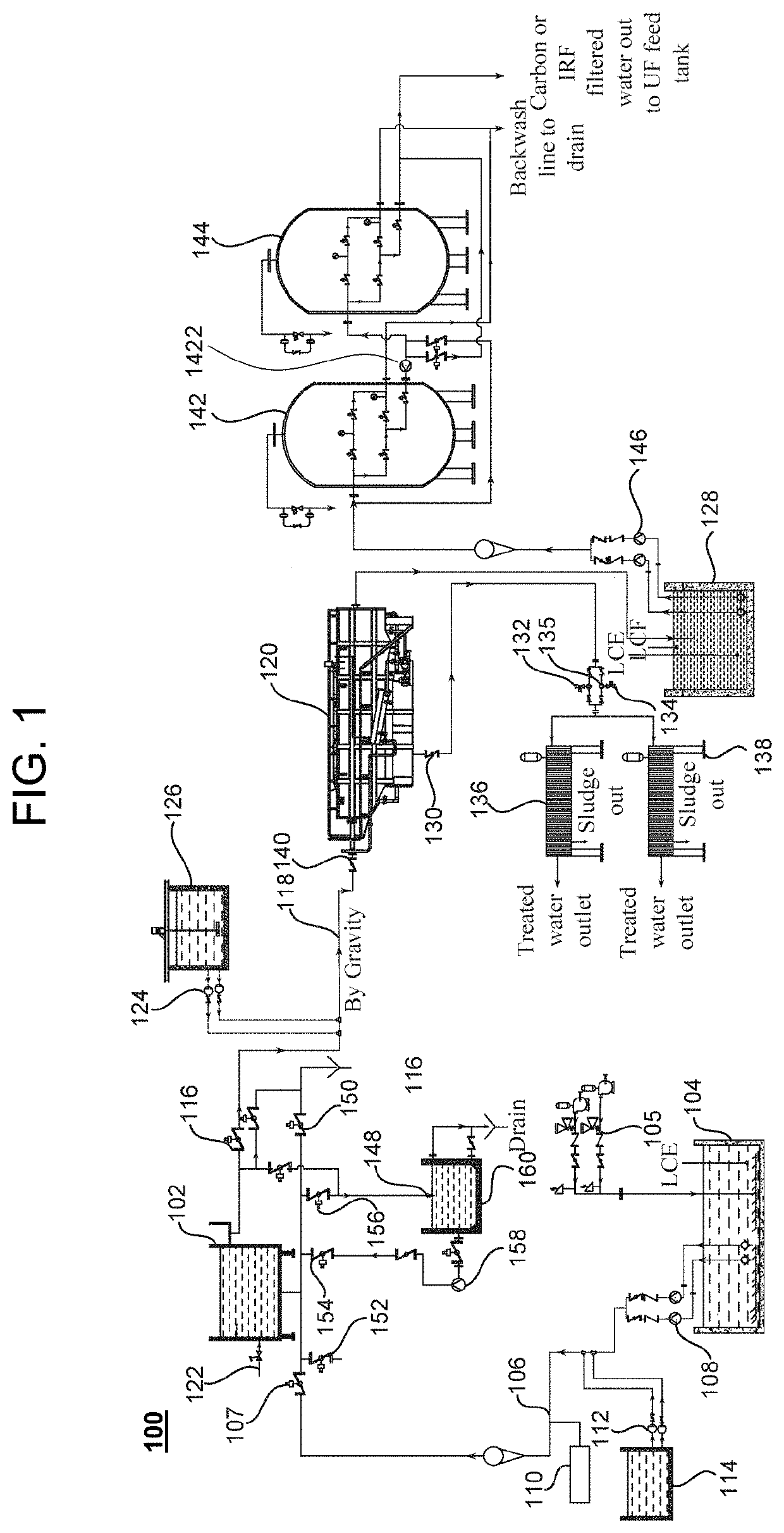
An automated waste water treatment system includes a collection tank constructed to hold waste water, a first flow line connected to the collection tank to output the waste water from the collection tank, an electrocoagulation unit that receives the waste water and outputs the waste water as coagulated waste water to a flow line, a polymer dosage tank to provide a polymer dosage into the flow line where the polymer dosage mixes with the coagulated waste water to produce and output flocculated waste water. A clarifier connected to the flow line receives the flocculated waste water and produces sludge-free waste water and concentrated sludge, a series of filters to output filter-treated water, and an ultrafiltration system that receives filter-treated water and outputs ultrafiltration-treated water to a reverse osmosis system.

Description

CROSS-REFERENCE TO RELATED APPLICATIONS[0001]This application claims priority to U. S. provisional patent application No. 62 / 736,265, filed on Sep. 25, 2018, and U. S. provisional patent application No. 62 / 799,657, filed on Jan. 31, 2019, the disclosures of which are incorporated herein by reference in their entirety.FIELD OF INVENTION[0002]Embodiments of this disclosure generally relate to waste water treatment, more particularly, to an automated waste water recycling system using advanced electro-coagulation unit.BACKGROUND OF THE INVENTION[0003]The term “waste water” is commonly used to refer to any of the numerous aqueous streams containing pollutants and contaminants that arise in industrial and other contexts. Such waste waters are also referred to as effluent. Some of the engineering and process industries effluents (waste water) that can be treated in the method, device, systems and processes according to the invention include, but are not limited to, the following industrie...

Claims


Application Information

Patent Timeline
IPC IPC(8): C02F9/00C02F1/00B01D25/12B01D24/10B01D24/46B01D61/02B01D61/08B01D61/14B01D61/18B01D61/58B01D21/01B01D21/30B01D21/24
CPCB01D21/302C02F1/004C02F1/56B01D61/022B01D21/245B01D61/145B01D21/01B01D61/58B01D61/18C02F2001/007C02F1/283C02F1/46104C02F2209/06B01D2311/18C02F1/008B01D2311/12B01D61/025B01D2311/2649C02F9/00C02F2001/46119C02F2201/46145B01D61/08C02F1/66B01D2317/025C02F1/441B01D2311/2626B01D2311/2661C02F2303/16B01D25/12C02F2201/005B01D2311/2642C02F1/444C02F2301/046B01D2311/2684B01D24/4636B01D24/10C02F2303/14C02F2209/40C02F2101/203C02F1/463C02F11/122C02F2201/4612C02F2301/08B01D61/04B01D2311/04B03D3/02B03D3/06B01D21/0006B01D21/0009B03D1/02B03D1/1431B01D61/026
Inventor KOH, MYUNGCHIDAMBARANATHAN, RATHNA KUMAR
Owner GREEN TECHNO CORP
Why Eureka
Try Eureka