Integrated selective capture, sequestration, fluidic isolation, electrical lysis and analysis of single cells

a selective capture and single cell technology, applied in the field of microfluidic devices, can solve the problems of mutated kras not being able to use this monotherapy, unable to reduce or eliminate ctcs after treatment, and difficult separation of ctcs from whole blood, the first inevitable step of overall analysis, etc., to achieve low cost, prevent assay crosstalk, and simplify fabrication

Active Publication Date: 2020-04-16
IOWA STATE UNIV RES FOUND
View PDF1 Cites 4 Cited by
  • Summary
  • Abstract
  • Description
  • Claims
  • Application Information

AI Technical Summary

Benefits of technology

[0020]Although the SD scheme is used to specifically address the need for an isolated reaction volume—an oil phase sealed off the narrow constrictions leading to the reaction chambers, there are three key distinctions for the claimed devices. First, there is only one fluidic layer, which greatly simplifies fabrication. Second, cell capture is accomplished at a micropocket other than a reaction chamber (i.e., not at the bottom of a reaction well), which critically provides independent control over the reaction volume in the reaction chamber and the capture efficiency at the micropocket. Third, and most importantly, the cell ...

Problems solved by technology

Differentiating or separating a few cells from a matrix or mixture containing multiple cell types is a challenging and exciting task that is in high demand.
Clinical studies have also shown that the reduction or elimination of CTCs after treatment prolongs survival.
For example, metastatic colorectal cancer patients with wild-type KRAS can benefit from anti-epidermal growth factor receptor (EFGR) monoclonal antibody (mAb) treatment, while those with mutated KRAS are not able to use this monotherapy.
Despite CTCs' promise as a clinical indicator and therapeutic target, the separation of CTCs from whole blood, which is the first inevitable step of overall analysis, is challenging.
However, the disclosed devices in Ser. No. 15/793,587 ap...

Method used


Image

  • Integrated selective capture, sequestration, fluidic isolation, electrical lysis and analysis of single cells
  • Integrated selective capture, sequestration, fluidic isolation, electrical lysis and analysis of single cells
  • Integrated selective capture, sequestration, fluidic isolation, electrical lysis and analysis of single cells

Examples


example 1

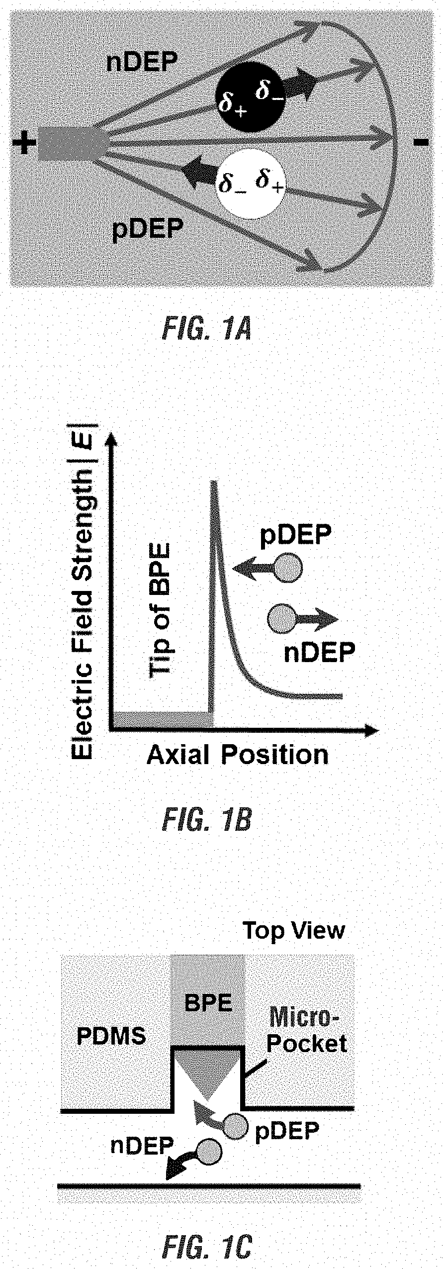
[0175]Design of the cell assay units in the microfluidic devises disclosed herein In the existing microfluidic devices disclosed in U.S. patent application Ser. No. 15 / 793,587 for capturing single cells, cell-scale micropockets extruding from either side of microchannels ensure individual cells to be selectively captured at each BPE tip.

[0176]In the microfluidic devices disclosed herein, reaction chambers are introduced adjacent to the micropockets for isolation and store a necessary amount of reagent solution for single cell assay.

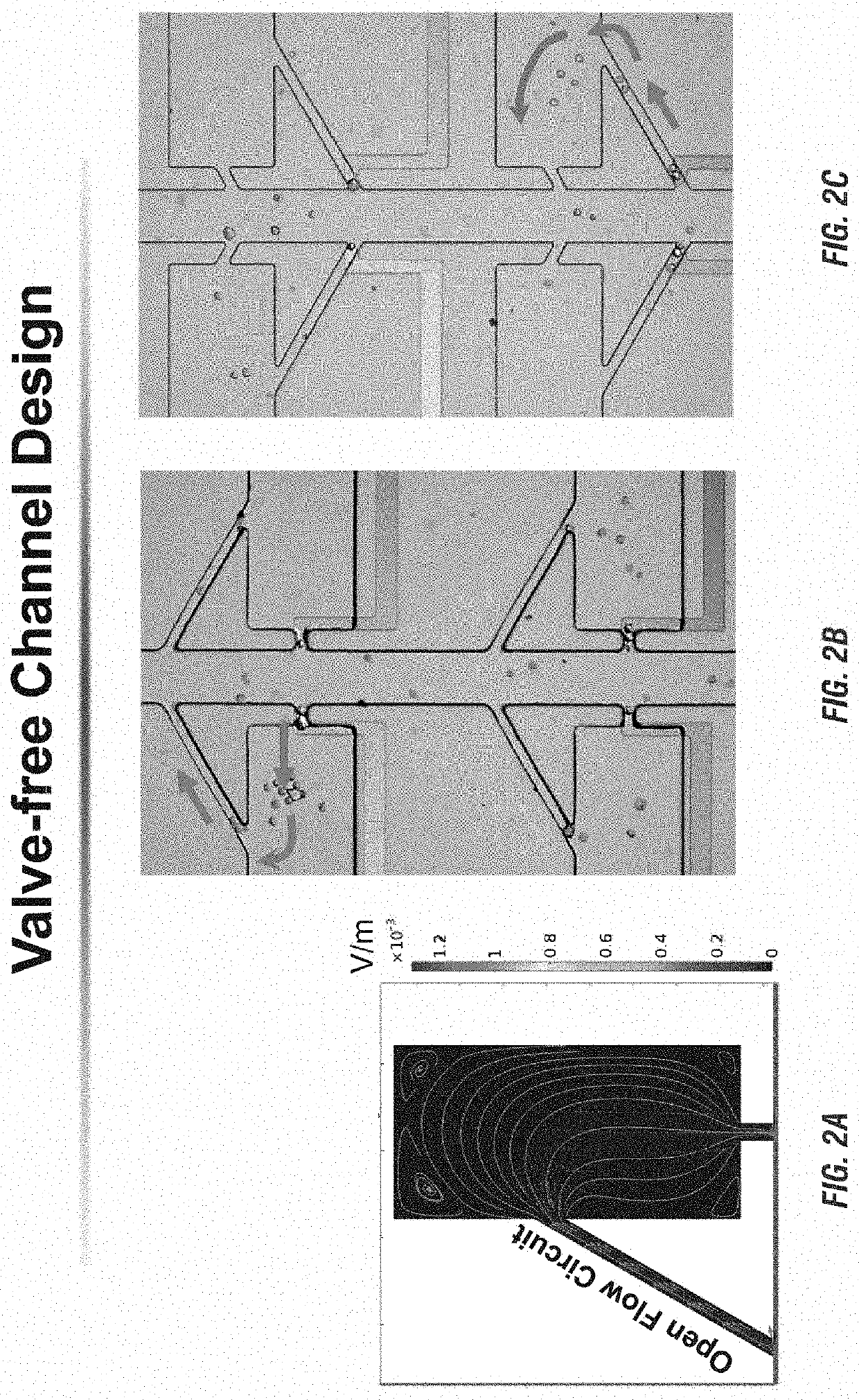
[0177]Transfer of each cell from a micropocket to its adjacent reaction chamber can be accomplished by increasing contact area between cells and reagents. FIG. 4A-FIG. 4D show the results of the cell transfer step in the absence of a leak channel. FIG. 4A shows a simulated contour plot for the flow velocity and streamlines of the device when a cell (represented by a white circle) is captured in the pocket. For this simulation, all pocket corners are fille...

example 2

Split BPE Design For Selective Recapturing and Retention of Individual Cells.

[0187]The leak channel design has successfully enabled capture and transfer of individual cells into reaction chambers. To integrate on-chip molecular analysis of single cells, the firm retention of isolated cells in the confined microstructures is crucial, especially in the case when fluid exchange is required. To address such demand, a split BPE design in which each single BPE employed previously was divided into two separate BPEs was developed as shown in FIG. 6A-FIG. 6F.

[0188]FIG. 6A-FIG. 6F show results of the cell re-capture step using split BPEs, time lapse images of cell capture, transfer, and recapture accomplished by only turning on and off the applied voltage. FIG. 6A shows cells flowing through channels when AC was off. FIG. 6B shows that turning on AC resulted in single-cell capture. FIG. 6C and FIG. 6D show that turning AC back off and then on enabled cell transfer and re-capture at the tips o...

example 3

Optimizing Cell Lysis

[0193]After cells were re-captured at the split BPEs, electric lysis was performed by increasing the applied voltage. To ensure rapid and gentle lysis, 5 s was initially chosen, and a voltage were applied and increased gradually until all the cells were lysed. Prior to cell lysis, the fluid flow in the fluidic microchannels was stopped to observe the static lysis. FIG. 7A-FIG. 7J show the results of using split BPEs inside the reaction chamber and a higher voltage to optimize cell lysis.

[0194]FIG. 7A and FIG. 7C show the bright field images of the cells re-captured at split BPEs. FIG. 7B and FIG. 7D show the captured cells moved to the center of the split BPEs after the voltage were increased to 166 Vpp to initiate lysis for 1 second. FIG. 7E, and FIG. 7H show the fluorescent images of the captured single MDA-MB-231 cells (green). FIG. 7F and FIG. 7I show the fluorescent images after the lysis of the captured single MDA-MB-231 cells after AC field application fo...


PUM


Abstract

A microfluidic device comprising one or more fluidic microchannels and one or more arrays of cell assay units is disclosed. Each cell assay unit in turn comprises at one bipolar electrode, micropocket, reaction chamber, and leak channel. In some embodiments, the cell assay unit further comprises two or more split BPEs inside the reaction chamber. The disclosed microfluidic device can be used to separate cells, especially rare cells, from its biological matrix and then analyze the isolated cell inside the reaction chamber. The disclosed device can isolate and analyze cells in a high-throughput fashion and without any modification or labelling to the cells. Cells isolated using the disclosed devices does not lose their vitality.

Description

CROSS-REFERENCE TO RELATED APPLICATION[0001]This application claims priority under 35 U.S.C. § 119 to Provisional Application U.S. Ser. No. 62 / 741,662, filed on Oct. 5, 2018, which is herein incorporated by reference in its entirety including without limitation, the specification, claims, and abstract, as well as any figures, tables, or examples thereof.FIELD OF THE INVENTION[0002]The present invention relates to a microfluidic device for selective single-cell capture at an array of wireless bipolar electrodes (bipolar electrodes, BPEs), i.e., selective cell isolation, retention, necessary reagent exchange, fluidic isolation, and rapid electrical lysis for high-throughput analysis. The device is capable of not only capturing a targeted cell but also of manipulating and preparing the captured cell for high-throughput analysis simply by exchanging the solution in a single inlet reservoir and by adjusting the applied voltage at a pair of driving electrodes. The device is thus well-suit...

Claims


Application Information

Patent Timeline
IPC IPC(8): B01L3/00B03C5/00C12N13/00
CPCB01L2300/0645B01L2300/023C12N13/00B03C5/005B01L3/502715B01L2200/0647B01L2300/12B03C5/026B03C2201/26B01L2400/0424B01L3/502761B01L2200/0668B01L2300/0864
Inventor ANAND, ROBBYN K.LI, MIN
Owner IOWA STATE UNIV RES FOUND
Why Eureka
Try Eureka