
Production of reactive oxidative species by photocatalytic activation of chlorine (i) under ultraviolet/visible light/near infrared irradiation

a technology of photocatalytic activation and reactive oxidative species, which is applied in the direction of oxidation, water/sewage treatment, and separation processes, etc., can solve the problems of unrecognized process, reactive oxidative species from free chlorine activation by less energy-intensive ultraviolet light, and energy-intensive uv irradiation

Active Publication Date: 2020-05-28
THE HONG KONG UNIV OF SCI & TECH
View PDF0 Cites 1 Cited by
  • Summary
  • Abstract
  • Description
  • Claims
  • Application Information

AI Technical Summary

Benefits of technology

The invention is about a system and method for producing reactive oxidative species by combining a source of chlorine, a solid photocatalyst, and a source of electromagnetic radiation. The photocatalyst is in direct contact with the chlorine-containing fluid, which can be water, groundwater, wastewater, or potable water. The system can be designed to create hydroxyl radicals, superoxide radicals, chlorine containing radicals, or singlet oxygen, which can be used for various purposes such as water decontamination, mold control, and organic synthesis. The method involves irradiating the photocatalyst with electromagnetic radiation and the resulting reactive oxidative species can be used in the same fluid or in another fluid. The patent text provides an example of a method where water containing a micro-contaminant is irradiated with electromagnetic radiation using a flow through cell with reflectors to optimize light absorption.

Problems solved by technology

However, activation of free chlorine by UV irradiation remains energy intensive and environmental unfriendly.
Yet, the production of reactive oxidative species from the free chlorine activation by a less energy intensive ultraviolet / visible light / near infrared light photocatalytic process is not disclosed.

Method used


Image

  • Production of reactive oxidative species by photocatalytic activation of chlorine (i) under ultraviolet/visible light/near infrared irradiation
  • Production of reactive oxidative species by photocatalytic activation of chlorine (i) under ultraviolet/visible light/near infrared irradiation
  • Production of reactive oxidative species by photocatalytic activation of chlorine (i) under ultraviolet/visible light/near infrared irradiation

Examples


Embodiment Construction

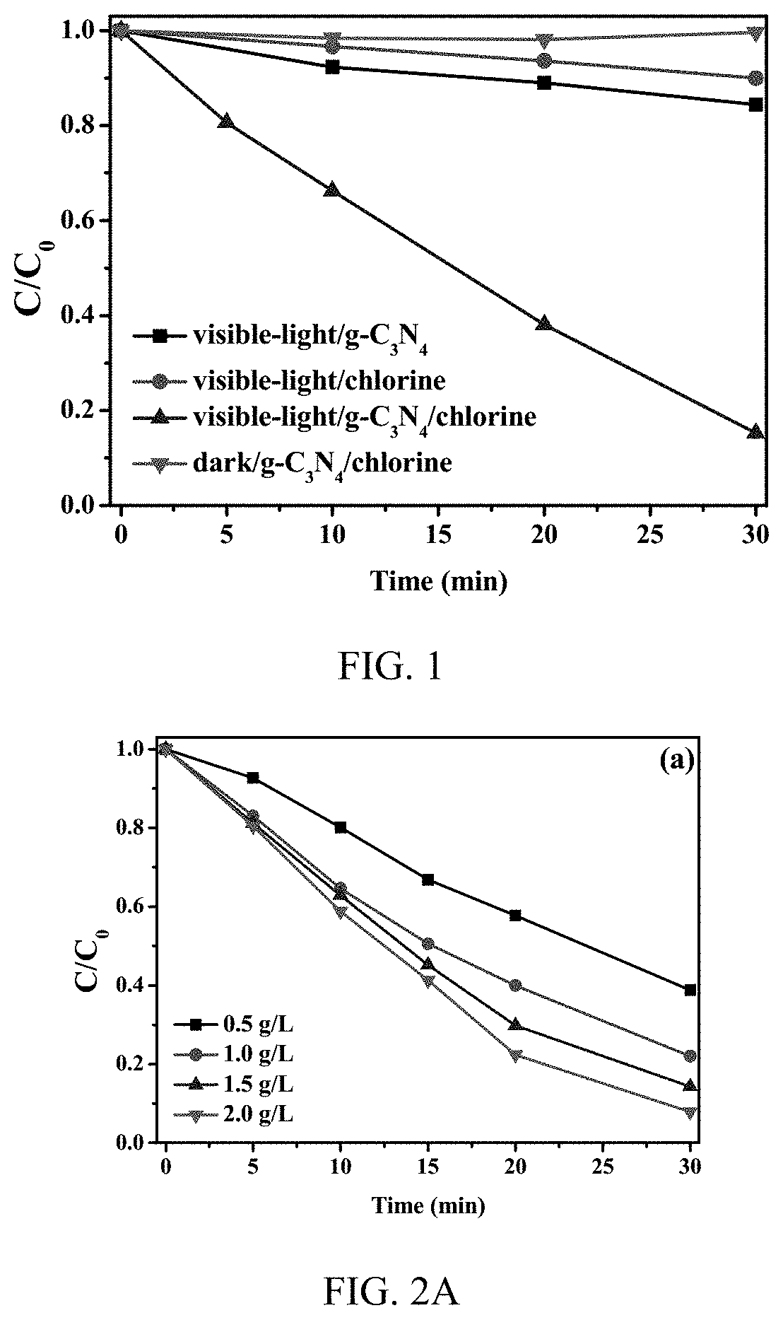
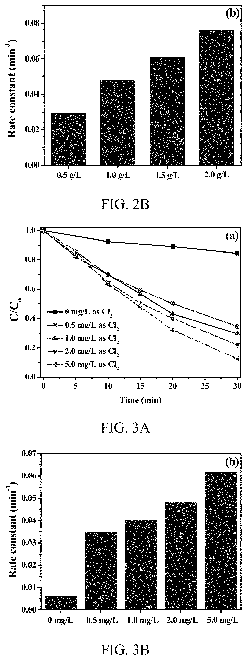
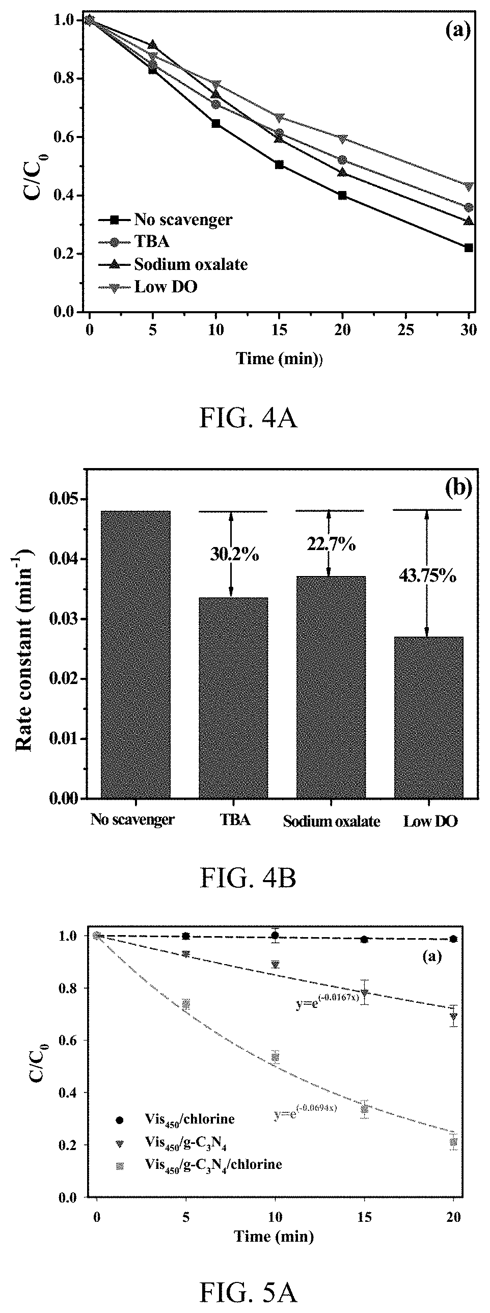
[0019]An embodiment of the invention is directed to the formation of reactive oxidative species by an AOP using photocatalysts that are activated by UV, visible and near infrared light. Various types of lamps, LEDs or sunlight can be used as the light source, where a suitable irradiation induces a photocatalyst to generate photoinduced species that activate chlorine. The activation of chlorine by this process can form various reactive oxidative species. The process activates chlorine using electrons, holes, and superoxide radicals that are generated after photocatalysts are activated by either UV or visible light or infrared. This activation produces larger amount of reactive oxidative species than the direct photolysis of chlorine under UV light and enables the activation of chlorine to form radicals by visible light or infrared radiation. The photocatalytic process forms a significant amount of electrons, holes, and superoxide radicals upon light irradiation using, singularly, or ...


PUM

PropertyMeasurementUnit
electromagneticaaaaaaaaaa
second-order reaction rate constantaaaaaaaaaa
electromagnetic radiationaaaaaaaaaa

Abstract

A system to produce reactive oxidative species in a fluid medium containing a source of Cl(I) by irradiating a solid photocatalyst suspended in the fluid medium or residing on a surface that is contactable by the fluid with electromagnetic radiation. The electromagnetic radiation can be in the UV, near-UV, visible, or near-IR consistent with the photocatalyst employed. The source of Cl(I) in certain embodiments is Cl2, HOCl, or H2NCl. The photocatalyst is g-C3N4, TiO2, BBiOBr, or any other solid insoluble photocatalyst.

Description

CROSS-REFERENCE TO RELATED APPLICATION[0001]This application claims the benefit of U.S. Provisional Application Ser. No. 62 / 917,202, filed Nov. 28, 2018, which is hereby incorporated by reference in its entirety including any tables, figures, or drawings.BACKGROUND OF THE INVENTION[0002]The UV / chlorine advanced oxidation process (AOP) is an emerging technology for degrading micro-pollutants in drinking water treatment. Currently, activation of chlorine is based on the dissociation of HOCl into hydroxyl radical and chlorine radical under UV irradiation. Even solar photolysis requires activation in the UV-A / UV-C range. The process produces hydroxyl radicals (HO.) and reactive chlorine species, which complement each other in the contaminant degradation. Unreacted free chlorine after the UV / chlorine AOP provides residual protection in water distribution systems. Furthermore, the UV / chlorine AOP reduces the disinfection byproduct formation and toxicity during the post-chlorination stage,...

Claims


Application Information

Patent Timeline
Patent Type & Authority Applications(United States)
IPC IPC(8): C02F1/32C02F1/72C02F1/76
CPCC02F1/725C02F1/32C02F1/763C02F1/50C02F1/76A01N59/00B01D53/74C02F2101/34B01D2251/108C02F1/30C02F2201/3222C02F2305/10C02F2303/04C02F2103/06
Inventor SHANG, CHIILING, LICHENG, ZIHANG
Owner THE HONG KONG UNIV OF SCI & TECH
Learn More