Clamshell material flow amplifier

a technology of material flow and amplifier, which is applied in the direction of conveyers, mechanical equipment, transportation and packaging, etc., can solve the problems of high cost of component wear, high cost of component replacement, and increase head loss of flowable material, so as to reduce the magnitude of laminar flow, increase the flow rate, and reduce the wear of the inner pipeline

Active Publication Date: 2020-06-04
VORTEX PIPE SYST LLC
View PDF17 Cites 9 Cited by
  • Summary
  • Abstract
  • Description
  • Claims
  • Application Information

AI Technical Summary

Benefits of technology

[0011]Embodiments of the present invention are directed to a device that overcomes drawbacks associated with known adverse flow conditions in pipe structures through a mechanical flow pumping device or a gravity flow system (e.g., surface erosion, head losses, fluid cavitation, heating, etc.) that arise from flow of certain types of materials (e.g., fluids, slurries, particulates, flowable aggregate, and the like) through a material flow conduit. A material flow amplifier in accordance with one or more embodiments of the present invention provides for flow of flowable material within a flow passage of a material flow conduit (e.g., a portion of a pipeline, tubing or the like) to have a cyclonic flow (i.e., vortex or swirling) profile. Advantageously, such a cyclonic flow profile centralizes flow toward the central portion of the flow passage, thereby reducing magnitude of a laminar flow. Such cyclonic flow profile provides a variety of other advantages as compared to a parabolic flow profile resulting from laminar flow (e.g., increased flow rate, reduce inner pipeline wear, more uniform inner pipe wear, reduction in energy consumption, reduced or eliminated slugging and the like).

Problems solved by technology

In association with this reduced velocity, the laminar flow effect (e.g., friction at the surface of the material flow conduit) is known to increase head loss and heating of the flowable material.
Transport and pumping flowable material comprising abrasive contents, such as coal and sand slurries, wet sand, gravel and the like can cause especially high costs associated with component wear due to interaction between the flowable material and the surface defining the passage through which such material flows.
Additionally, uneven erosion in piping systems, especially elbow fittings, is well known to lead to fitting failure or early fitting replacement, either of which is costly in material, manpower and downtime.
This change in direction may also create standing eddies causing backflow conditions at points along the elbow fitting pipe walls.
These conditions generally cause the elbow fitting pipe wall along the outside of the bend to erode substantially faster than the pipe wall along the inside of the bend because the flowable material impinges directly against the wall along the outside of the bend as it enters the fitting and changes direction.
Additionally, due to centrifugal force, heavier solids and particulates are generally thrown to the outside wall as the flowable material changes direction and tend to continually scour the outer wall.
Additionally, in large diameter piping systems, the weight of the flowable material is borne by the lower pipe wall portion thereby causing higher erosion rates.
However, higher pumping pressures are generally implemented at the expense of higher energy consumption and associated cost.
Additionally, implementation of higher pumping pressures often creates vibration and heating problems in the piping system.
However, long radius fittings require a great deal of space relative to standard (i.e., short) radius fittings.
Additionally, long radius fittings still suffer accelerated erosion rates along the pipe wall along the outside of the bend because centrifugal force still causes heavier, more abrasive flowable materials to be thrown to the outer wall, and they are continually scoured by on-going flow of such flowable material.

Method used


Image

  • Clamshell material flow amplifier
  • Clamshell material flow amplifier
  • Clamshell material flow amplifier

Examples


Embodiment Construction

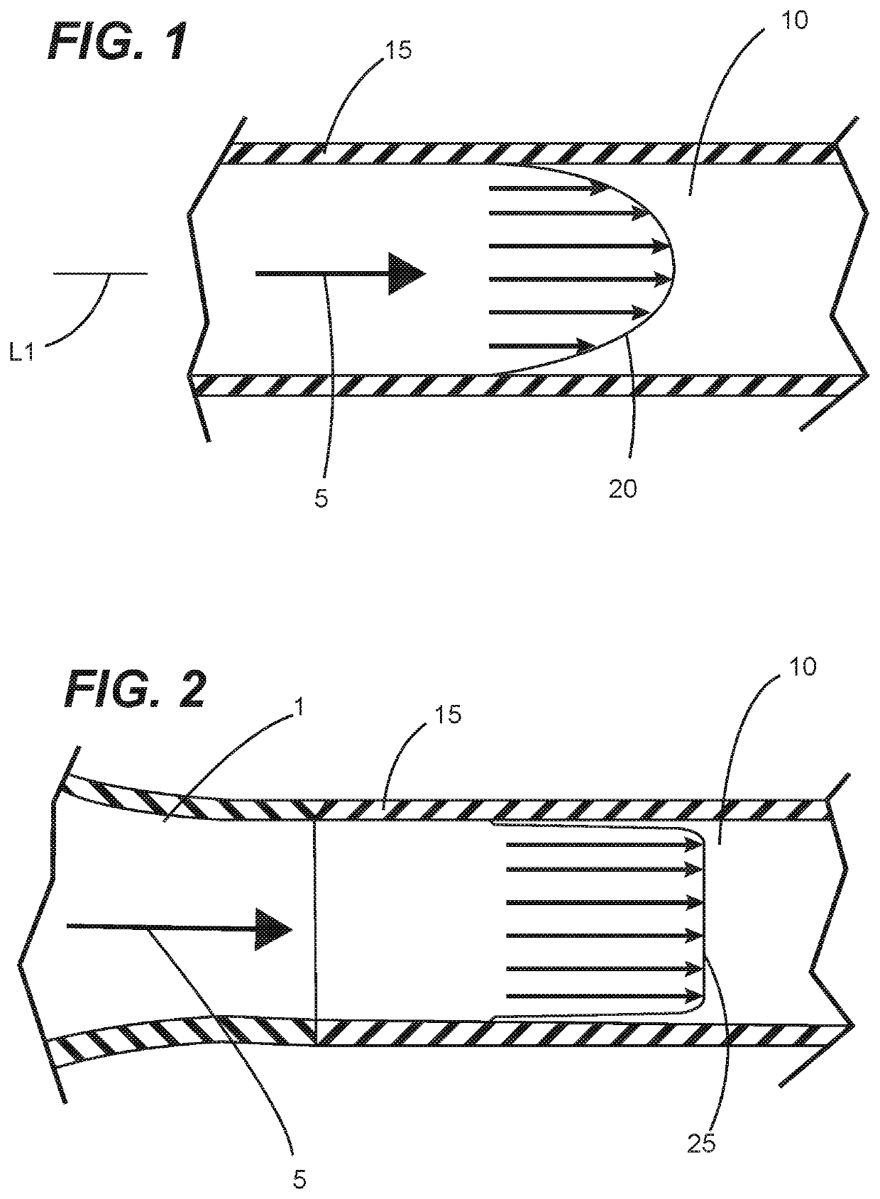
[0037]Embodiments of the present invention are directed to material flow amplifiers that provide for increased volumetric flow rates for flowable material (e.g., fluids, slurries, particulates, flowable aggregate, and the like) and reductions in wear to material flow conduits through which flow of such flowable materials is provided. These material flow amplifiers induce a cyclonic (i.e., a vortex or swirling) flow profile that advantageously overcomes drawbacks associated with known adverse flow conditions (e.g., internal pipe wall erosion, head losses, material heating) that can arise from flow of various types of flowable materials flowing through a material flow conduit in a conventional manner (e.g., under laminar flow effect).

[0038]As discussed above in reference to FIG. 1, conventional of flowable material 5 within a flow passage 10 of a material flow conduit 15 has a flow profile characterized by laminar flow effect (i.e., laminar flow 20). However, advantageously, material ...


PUM

PropertyMeasurementUnit
angular rotationaaaaaaaaaa
diameteraaaaaaaaaa

Abstract

Material flow amplifiers as disclosed herein overcome drawbacks associated with known adverse flow conditions (e.g., surface erosion and head losses) that arise from flow of certain types of materials (e.g., fluids, slurries, particulates, flowable aggregate, and the like) through a material flow conduit. Such material flow amplifiers provide for flow of flowable material within a flow passage of a material flow conduit (e.g., a portion of a pipeline, tubing or the like) to have a cyclonic flow (i.e., vortex or swirling) profile. Advantageously, the cyclonic flow profile centralizes flow toward the central portion of the flow passage, thereby reducing magnitude of laminar flow. Such cyclonic flow profile provides a variety of other advantages as compared to a parabolic flow profile (e.g., increased flow rate, reduce inner pipeline wear, more uniform inner pipe wear, reduction in energy consumption, reduced or eliminated slugging and the like).

Description

CROSS-REFERENCE TO RELATED APPLICATIONS[0001]This continuation patent application claims priority from co-pending United States Non-Provisional patent application Ser. No. 16 / 445,127, filed 18 Jun. 2019, entitled “MATERIAL FLOW AMPLIFIER”, having a common applicant herewith and being incorporated herein in its entirety by reference. Co-pending U.S. Non-Provisional patent application Ser. No. 16 / 445,127 claims priority from co-pending U.S. Provisional patent application Ser. No. 62 / 917,233, filed 29 Nov. 2018, entitled “MULTI-CHAMBERED VORTEX PIPELINE AMPLIFIER (FULLY PIGGABLE)”, having a common applicant herewith and being incorporated herein in its entirety by reference.FIELD OF THE DISCLOSURE[0002]The disclosures made herein relate generally to structural devices used for transmission of flowable materials and, more particularly, to devices used for enhancing flow attributes of material within a material flow conduit such as a pipeline or a tubular flow member.BACKGROUND[0003]The ...

Claims


Application Information

Patent Timeline
Patent Type & Authority Applications(United States)
IPC IPC(8): F15C1/18B01F5/06B01F23/00B01F23/47
CPCB01F5/0614B01F5/0651B01F5/0659B01F5/064F15C1/18F17D1/20F15D1/0015F15D1/04F16L55/02772F16L57/06B65G53/521B01F25/432B01F25/435B01F25/4314B01F25/4334
Inventor SCHMIDT, PAUL WAYNEGHOSH, AVIJIT
Owner VORTEX PIPE SYST LLC
Why Eureka
Try Eureka