Monolithic transmitting spectral beam combiner

a spectral beam and combiner technology, applied in the direction of instruments, laser details, monitoring arrangements, etc., can solve the problems of unfavorable laser damage threshold, long optical path, and inability to adjust the spacing of the grating, so as to achieve less volume and weight, high laser damage threshold, and less cost

Active Publication Date: 2020-06-04
LAWRENCE LIVERMORE NAT SECURITY LLC
View PDF0 Cites 0 Cited by
  • Summary
  • Abstract
  • Description
  • Claims
  • Application Information

AI Technical Summary

Benefits of technology

[0017]5. Extremely high laser damage thresholds are sustainable—it can be made 100% from bulk fused silica material, no thin film is needed.
[0018]FIG. 2 provides some comparisons of the use of the transmission grating of the present invention for spectral beam combining versus using a reflection grating configuration. The present monolithic assembled transmission grating spectral beam combiner offers several advantages over reflection grating spectral beam combiner. For example, transmission designs have less volume and weight. They can accommodate at least 20× more fluence due to the use of bulk SiO2 material without thin film coatings. The transform lens can be round and can be close to the grating where beams come to overlap at the grating. Fiber launch points for each wavelength can be arranged along linear spacing without the conical “smile” needed in reflection grating designs. The present invention can cost less than conventional designs. A targeting scope is colinear with the output beam path working at half the beam wavelength (which transmits through the transmission grating) which is not possible with reflection grating designs.

Problems solved by technology

If each input beam is diffraction limited and high-quality optics are used, the combined output beam also will be diffraction limited.
1. Requires long optical path lengths. For high efficiency performance, the reflective beam combiner is required to be oriented at the Littrow angle for the desired central wavelength, where input beam and output laser beams are at the identical angle, only separated by a very small vertical angle offset, typically less than 4 degrees. Separating the input and output beam for this configuration requires a long optical path.
2. Vertical angle offset creates a “conical mount” configuration where the incoming beams are not normal to the diffraction grating grooves. This “out of plane” geometry causes an undesired change in grating spacing that needs to be compensated for by placing each wavelength fiber source at adjacent points along a conical arc segment “smile”.
3. Alignment sensitive. Because of the long optical path lengths and since reflection surface angular changes are magnified 2× on the beam leaving the mirror like-grating lines, the optics components are typically free-space, thus the alignment of these system are very sensitive and difficult to make mechanically robust.

Method used


Image

  • Monolithic transmitting spectral beam combiner
  • Monolithic transmitting spectral beam combiner
  • Monolithic transmitting spectral beam combiner

Examples


Embodiment Construction

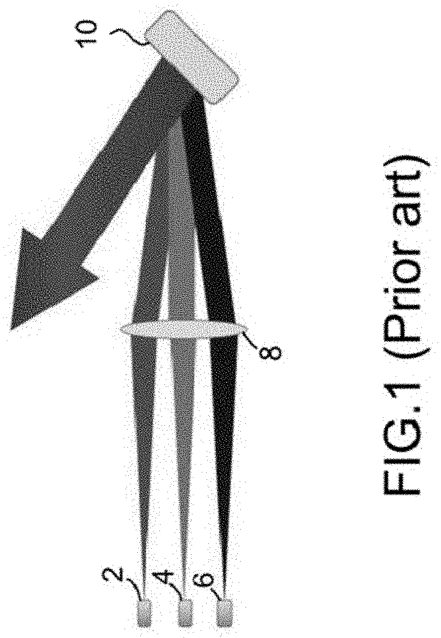
[0033]The present device consists of a monolithic structure, such as a hollow tube, where in the input end cap consist of a transform optic and the output end cap consist of a transmission grating.

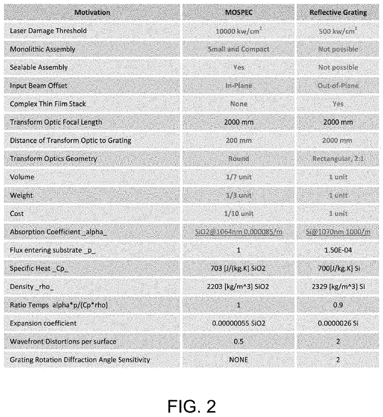
[0034]This monolithic spectral beam combiner device has numerous significant advantages over the tradition reflectance combining optical elements, such as:

[0035]1. It is significantly more compact.

[0036]2. The monolithic configuration is less sensitive to misalignment, can be sealed to minimize environmental contamination (no critical surfaces are expose to external environment) and can be self thermally compensating.

[0037]3. It can have an in-plane configuration—no need to compensate for change in grating spacing.

[0038]4. Extremely high laser damage threshold is available. It can be made 100% from bulk fused silica material and no thin film is needed.

[0039]5. To minimize the Fresnel reflection losses, both the input and output surfaces can utilize bulk microstructure features.

[0040]6. The...


PUM

PropertyMeasurementUnit
wavelengthsaaaaaaaaaa
grating depthaaaaaaaaaa

Abstract

A device utilized for spectrally combining multi lasers or laser emitters into a single high-power beam. Exemplary embodiments of the device consist of a monolithic structure, such as a hollow tube, wherein the input end cap comprises a transform optic and the output end cap comprises a transmission grating.

Description

CROSS-REFERENCE TO RELATED APPLICATIONS[0001]This application claims the benefit of U.S. Provisional Patent Application No. 62 / 774,694 titled “Monolithic Transmitting Spectral Beam Combiner,” filed Dec. 3, 2018, incorporated herein by reference. This application claims the benefit of U.S. Provisional Patent Application No. 62 / 821,653 titled “Monolithic Transmitting Spectral Beam Combiner,” filed Mar. 21, 2019, incorporated herein by reference.STATEMENT AS TO RIGHTS TO INVENTIONS MADE UNDER FEDERALLY SPONSORED RESEARCH OR DEVELOPMENT[0002]The United States Government has rights in this invention pursuant to Contract No. DE-AC52-07NA27344 between the United State Department of Energy and Lawrence Livermore National Security, LLC, for the operation of Lawrence Livermore National Laboratory.BACKGROUND OF THE INVENTIONField of the Invention[0003]The present invention relates to spectral beam combining, and more specifically, it relates to the use of a transmission grating in a spectral b...

Claims


Application Information

Patent Timeline
Patent Type & Authority Applications(United States)
IPC IPC(8): G02B27/10G02B27/14
CPCG02B27/1013H01S3/0627G02B27/148H01S3/005H01S3/0071H01S3/2391H01S3/0014G02B27/1006G02B27/1086G02B5/1866
Inventor NGUYEN, HOANG T.RUSHFORD, MICHAEL C.
Owner LAWRENCE LIVERMORE NAT SECURITY LLC
Why Eureka
Try Eureka