Cardiac valve prosthesis

a prosthetic device and cardiac valve technology, applied in the field of implantable prosthetic devices, can solve the problems of inability to fully function, and inability to fully function, and achieve the effect of reducing the capacity of filler materials, effective fluid tightness, and increasing circumferential exten

a prosthetic device and cardiac valve technology, applied in the field of implantable prosthetic devices, can solve the problems of inability to fully function, and inability to fully function, and achieve the effect of reducing the capacity of filler materials, effective fluid tightness, and increasing circumferential exten

US20200179113A1Pending Publication Date: 2020-06-11RIGHINI GIOVANNI

Image

  • Cardiac valve prosthesis
  • Cardiac valve prosthesis
  • Cardiac valve prosthesis

Examples


Embodiment Construction

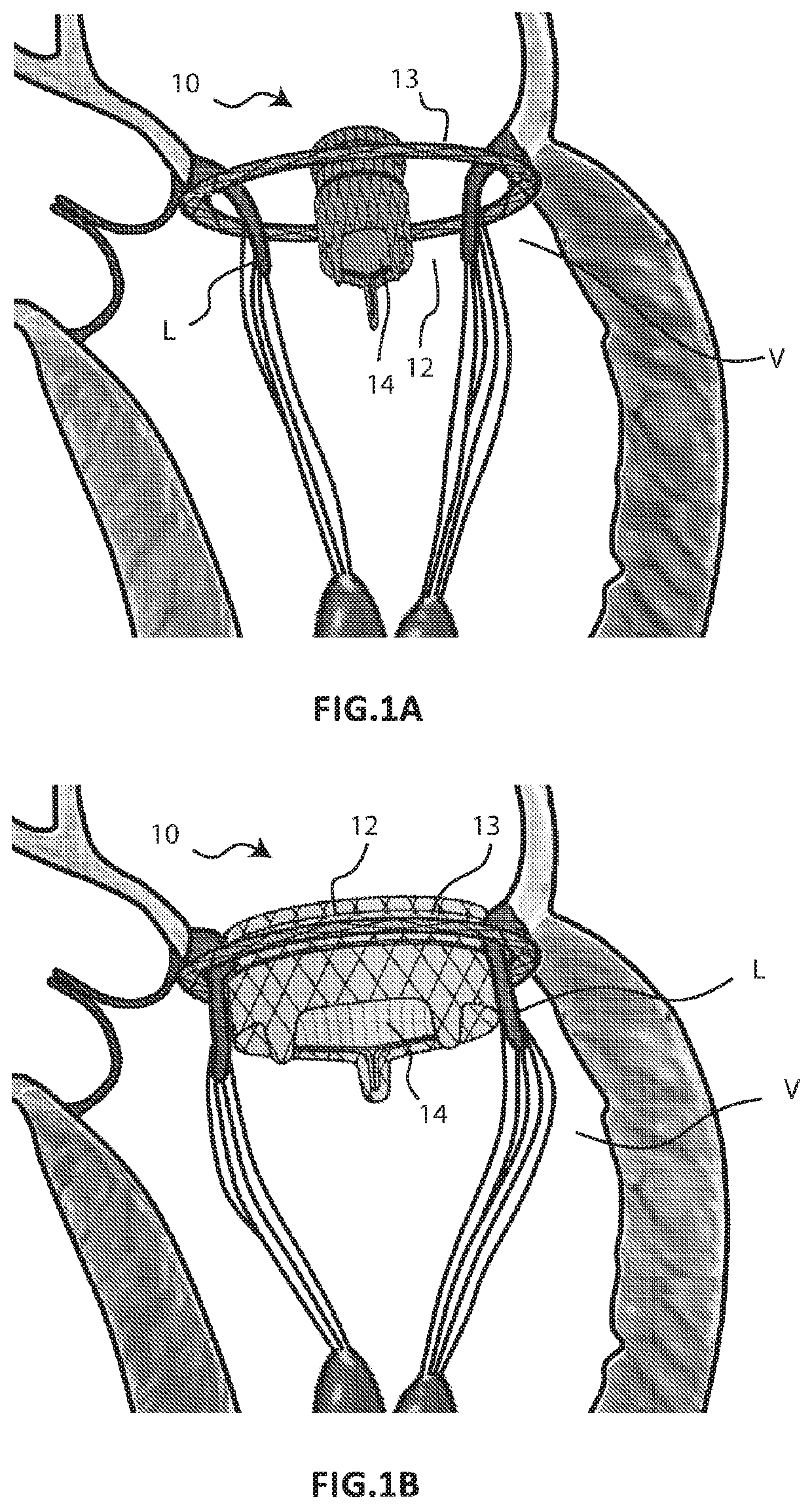
[0053]FIGS. 1A and 1B schematically illustrate two different steps of the implantation method of a prosthesis 10 for a cardiac valve according to the present invention, which prosthesis is used to replace the functionality of a native atrio-ventricular valve V to be treated. The prosthesis 10 comprises a first component in the form of an annular element 12 and a second component in the form of a central member 14, which supports prosthetic valve leaflets 16. During the implantation method, the annular element 12 is positioned outside the native atrio-ventricular valve V in order to completely surround it, while the central member 14 is expanded inside the same native atrio-ventricular valve V (FIG. 1A). The expansion of the central member 14 causes the two components 12, 14 to be connected to each other (FIG. 1B). The contact between the two components 12, 14 is not direct but instead occurs with the interposition of the leaflets L of the native valve V which remain interpolated bet...


PUM

PropertyMeasurementUnit
Young's modulusaaaaaaaaaa
volumeaaaaaaaaaa
pressureaaaaaaaaaa

Abstract

A prosthesis for a cardiac valve includes prosthetic leaflets which are intended to functionally replace the native leaflets of a cardiac valve following the implantation of the cardiac prosthesis. The prosthesis also includes a prosthetic member on which there are mounted the prosthetic leaflets and which is intended to take up a stable, predetermined functional configuration in which the prosthetic member and the prosthetic leaflets reproduce the functionally correct configuration for the purpose of the physiological replacement of the native cardiac valve. The prosthetic member is preconfigured so as to move gradually from an altered, temporary functional configuration, in which the prosthetic member has a deformed geometry with respect to the stable, predetermined stable functional configuration, to said stable, predetermined functional configuration.

Description

CROSS-REFERENCE TO RELATED APPLICATIONS[0001]This is a divisional of prior U.S. application Ser. No. 16 / 062 020, filed Jun. 13, 2018, which is a National Phase application of PCT Application No. PCT / IB2016 / 057646, filed Dec. 15, 2016, the entire contents of which is hereby incorporated herein in its entirety.FIELD OF APPLICATION[0002]The present invention relates to the field of implantable prosthetic devices for the treatment of malfunctions of cardiac valves.[0003]The invention has been developed with particular regard to an implantable prosthetic device which is capable of replacing the physiological function of a malfunctioning cardiac valve.TECHNOLOGICAL BACKGROUND[0004]Cardiac valves are organs which preside over the correct functioning of the heart as a pump for the generation of blood flow in the circulation system of living beings. The main objective thereof involves making the blood flow unidirectional inside the cardiac cavities, being essential both in the filling phase ...

Claims


Application Information

Patent Timeline
11 Jun 2020
Publication
US20200179113A1
IPC
A61F2/24
CPC
A61F2210/0004; A61F2/2418; A61F2/2412; A61F2250/001; A61F2220/0025; A61F2250/0063; A61L27/58; A61L2430/20
Inventors
RIGHINI, GIOVANNI