High-resolution uhf near-field imaging probe

a near-field imaging and high-resolution technology, applied in the field of imaging, can solve the problems of reducing the penetration of signal into the test object, limiting the utility of the probe for imaging high-loss samples, increasing the implementation cost and complexity of the imaging system, etc., and achieves low complexity, high resolution, and high resolution.

Active Publication Date: 2020-07-02
KHALIFA UNIV OF SCI & TECH
View PDF0 Cites 1 Cited by
  • Summary
  • Abstract
  • Description
  • Claims
  • Application Information

AI Technical Summary

Benefits of technology

[0017]Aperture probes such as rectangular and circular apertures have been extensively used for near-field microwave imaging. The imaging resolution offered by these probes is in the order of the aperture dimensions. For a given aperture to radiate efficiently, its largest dimension should be a good fraction of the operating wavelength (λ), e.g., λ/2. Consequently, it is necessary to work at high microwave frequencies to obtain spatial resolutions in the order of few millimeters when aperture probes are used. On the other hand, near-field imaging based on apertures loaded with resonators probes has shown to provide high resolution while operating at a relatively low microwave frequencies. Remarkably, planar open resonator probes such as split r...

Problems solved by technology

Operating in frequencies in these bands reduces the signal penetration into the test object, and this in turn limits the utility of the probe for imaging high loss samples.
Furthermore, the implementation cost and complexity of the imaging system increases as the frequency increase.
While reducing the operating frequency grants deeper inspection, it impacts the imaging resolution.
For many reasons, the array design becomes an inevitable hurdle for practical imager realization at high microwave frequencies.
The desired mono-static based microwave imaging systems use the same array element for transmitting and receiving, and hence, they require complex circuitry for signal routing and detection.
The circuit components introduce additional losses at high frequen...

Method used


Image

  • High-resolution uhf near-field imaging probe
  • High-resolution uhf near-field imaging probe
  • High-resolution uhf near-field imaging probe

Examples


Embodiment Construction

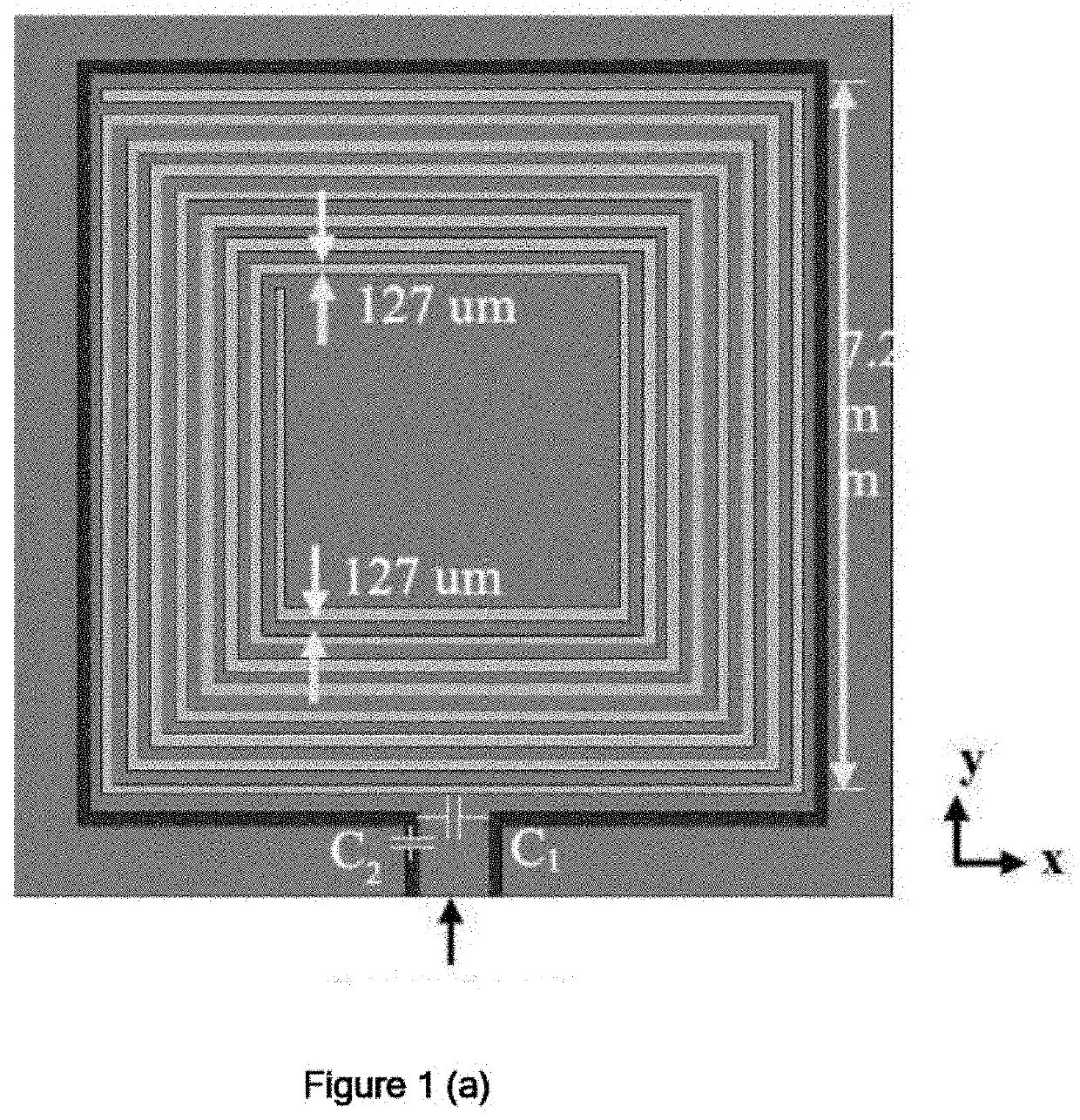
[0108]Various small resonators can be used to construct near-field microwave imaging sensors. Circular / square SRRs, CSRRs, circular / square SR and Fractal Hilbert curves are some of the prominent examples of such small resonators. Selecting a certain resonator depends on the desired quality factor, miniaturization requirements, manufacturability, and feeding constrains. For near-field imaging, the sensor is ought to have small footprint and offer high sensitivity. Consequently, the spiral resonator types which offer significant miniaturization rate (resonator dimension of the order of 0.01, is highly feasible) and high Q-factor are suitable candidate for near-field imaging. Furthermore, the SR could be efficiently excited using a simple loop yielding a one-port sensor.

[0109]The proposed microwave imaging sensor utilizes an 8-turn square shaped resonator similar to the unit cell used in and shown in FIG. 1(a). The SR 102 was made of copper stripes laid on RO 4350 1.5 mm-thick dielectr...


PUM


Abstract

The present invention discloses imaging antenna and array by designing the system in the Ultra-high frequency (UHF) band 300 MHz-3 GHz with resolution comparable to high-frequency microwave imagers (i.e., super-resolution). To obtain high resolution at relatively low system cost and complexity, a novel modulated antenna array element design is disclosed. The antenna is basically small loop loaded with spiral resonator. The selection of the SR as a resonator provides for adequate miniaturization rate at the lower end of the microwave frequency range. A non-modulated version of this antenna has been conceived and yielded a resolution comparable to the 24 GHz antennas while operating at 426 MHz. The disclosed antenna element operating at 426 MHz produced images with very comparable attributes to the one obtained at 24 GHz. In fact, it has been established that proposed antenna element yield a resolution of around 5 mm (much less that the wavelength divided by 100), and hence it provides super-resolution as long as the diffraction limit is concerned. The present invention further discloses an imaging probe unit comprising a imaging sensor loaded with a PIN diode, an L-matching circuit and an LC resonant detuning circuit. The present invention further discloses a one-dimensional array, comprising a plurality of imaging probe units which are placed side by side in very close proximity of each other.

Description

FIELD OF THE INVENTION[0001]The present invention relates to the field of imaging, more particularly to near-field microwave imaging.BACKGROUND OF THE INVENTION[0002]Background description includes information that may be useful in understanding the present invention. It is not an admission that any of the information provided herein is prior art or relevant to the presently claimed invention, or that any publication specifically or implicitly referenced is prior art.[0003]Near-field microwave imaging techniques have proven significant utility in the wide range of industrial applications including mapping of corrosion under thin coating inspection of composite materials and surface crack detection among others. These imaging techniques have evolved over the past years as potential alternative for the existing imaging modalities. In active near-field microwave imaging, an imaging probe is used to irradiate the object of interest with microwaves, while the object is placed in close pr...

Claims


Application Information

Patent Timeline
IPC IPC(8): G01N22/02H04N5/247
CPCG01N22/02H04N5/247H04N5/30G01R33/00G01R33/34H04N23/90
Inventor ABOU-KHOUSA, MOHAMED
Owner KHALIFA UNIV OF SCI & TECH
Why Eureka
Try Eureka