

Low-Reflection Coating Glass
a coating glass and low-reflection technology, applied in the field of low-reflection coating glass, can solve the problems of low visible-light transmittance and low visible-light reflectance, affect the infrared rays, and achieve the effect of high infrared-blocking ratio
- Summary
- Abstract
- Description
- Claims
- Application Information
AI Technical Summary
Benefits of technology
Problems solved by technology
Method used
Image

Examples
example 1
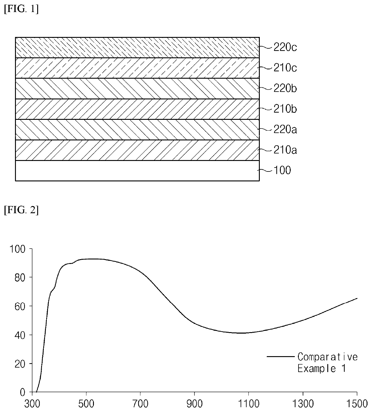
on of Low-Refection Coating Glass
[0053]Each dielectric layer having a thickness as shown in the following Table 1 was deposited on a 6 mm glass substrate, and thereby a low-reflection coating glass having a lamination structure as shown in the accompanying FIG. 1 was prepared. Each of the dielectric layers was deposited using magnetron sputtering equipment. The deposition was performed under the conditions of a chamber pressure of 3 mTorr to 5 mTorr and a power of 1 kW to 3 kW, using TiO2 and SiAl as targets. Accordingly, the first, third, and fifth dielectric layers included titanium oxide having a refractive index of 2.3, and the second, fourth, and sixth dielectric layers included silicon oxide having a refractive index of 1.45.
experimental example 1
ectance of Low-Reflection Coating Glass
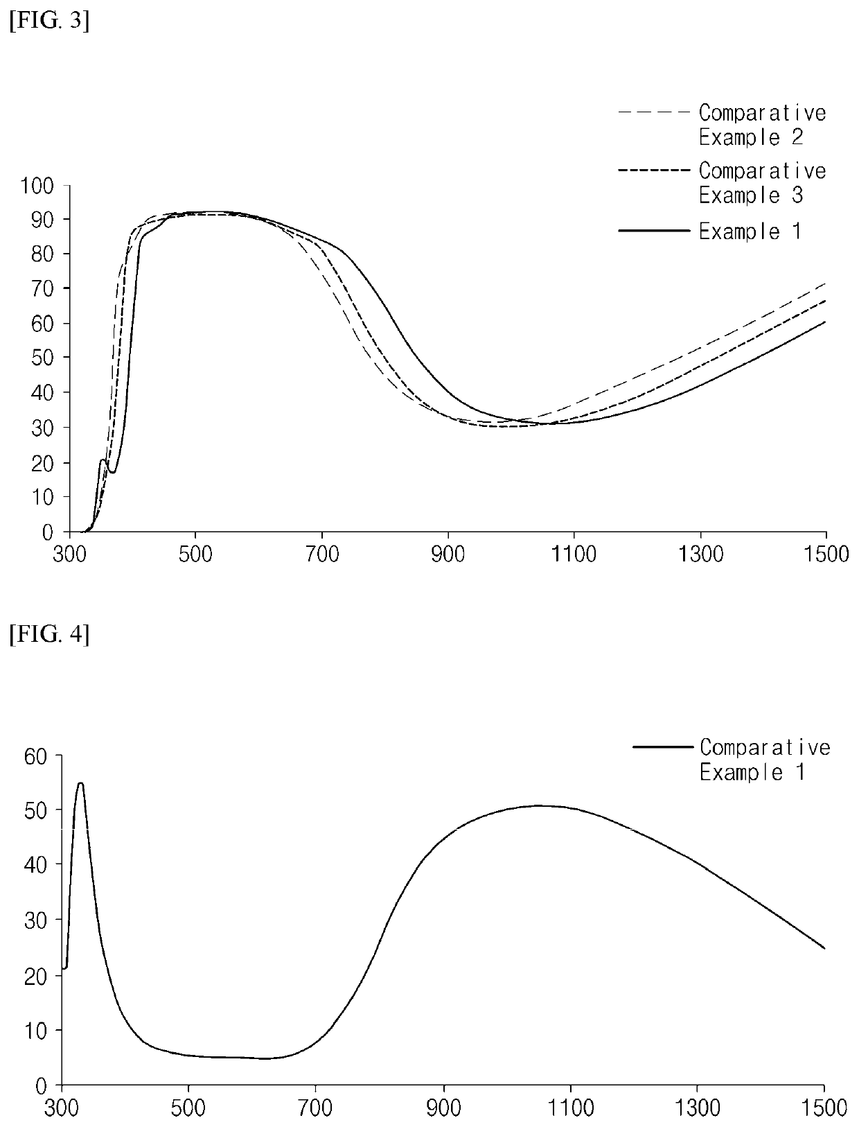
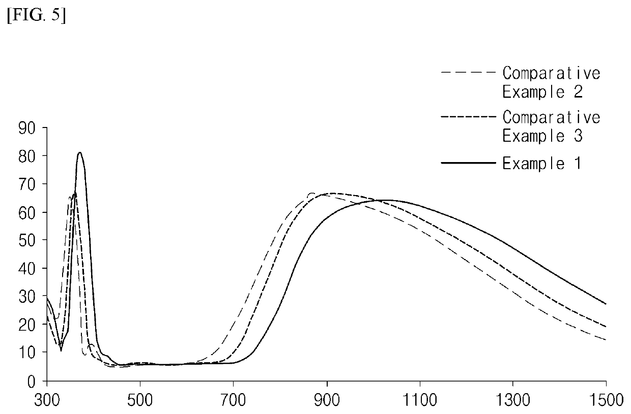
[0056]The transmittance and reflectance of the low-reflection coating glasses produced according to the Examples and the Comparative Examples were measured, in accordance with the KS L 2514 standard, in the 300 nm to 1,500 nm range using a LAMBDA 950 spectrophotometer (PerkinElmer, Inc., KS L 2514 standard), and the results thereof are shown in the following Table 2 and in FIGS. 2 to 5. The infrared-blocking ratio is defined as (100-infrared transmittance)%. Here, as shown in the following Table 2, the values of visible-light transmittance and visible-light reflectance were obtained in the 380 nm to 780 nm range, and the values of infrared-blocking ratio and infrared reflectance were obtained in the 780 nm to 2,500 nm range.
TABLE 2Compar-Compar-Compar-Exam-ativeativeativeple 1Example 1Example 2Example 3Visible-light transmittance91.4%92.3%91.4%91.1%Visible-light reflectance5.2%5.2%5.3%5.6%Infrared-blocking ratio50.4%44.0%51.2%52.2%Infrared refl...
PUM
| Property | Measurement | Unit |
|---|---|---|
| visible-light reflectance | aaaaa | aaaaa |
| visible-light reflectance | aaaaa | aaaaa |
| refractive index | aaaaa | aaaaa |
Abstract
Description
Claims
Application Information