Steel for coiled tubing with low yield ratio and ultra-high strength and preparation method thereof

a technology of coiled tubing and low yield ratio, which is applied in the direction of heat treatment equipment, manufacturing tools, furnaces, etc., can solve the problems of low strength of carbon steel coiled tubing, poor working conditions, and complicated stress conditions, and achieve high yield ratio, good processability, and high plasticity

Active Publication Date: 2020-08-13
BAOSHAN IRON & STEEL CO LTD
View PDF0 Cites 6 Cited by
  • Summary
  • Abstract
  • Description
  • Claims
  • Application Information

AI Technical Summary

Benefits of technology

[0043](1) In the present invention, through combination of adopting composition system of medium-low C, medium-high Mn and alloying, and appropriate techniques, high strength and high plasticity, good processability, and heat treatment adaptability of steel are achieved. A relatively high content of Cu and a relatively high content of Ni are added to obtain high strength and high corrosion resistance. The microalloying element V is added to achieve effects of grain refinement and precipitation strengthening, and an appropriate amount of Nb is added to further strengthen effects of grain refinement and precipitation strengthening, while avoiding continuous casting cracks. Cr element is added to promote the formation of ferrite and help to improve the corrosion resistance of steel. An appropriate amount of Mo element is added to promote bainite transformation, help to stabilize the retained austenite and improve or suppress the subsequent heat treatment brittleness. Low sulfur design is adopted and micro-Ca treatment is performed, so as to ensure that the steel has no elongated inclusions, and to improve the impact toughness and fatigue resistance.
[0044](2) In regard to the techniques of the present invention, by adopting techniques of relatively low temperature final rolling and low temperature coiling, and employing the phase transition control effect of Cr and Mo alloying elements, an MA constituents+bainite+ferrite multiphase structure is obtained, and a low yield ratio and an ultra-high strength are achieved. The steel has superior performances such as processability and heat treatment adaptability.
[0045](3) The steel according to the present invention has a yield strength (Rp0.2) of 620 MPa or more, a tensile strength (Rm) of 750 MPa or more, an elongation (A50) of 11% or more and a yield ratio (Rp0.2 / Rm) of 0.83 or less. Moreover, the steel has a good surface quality, a thickness uniformity and excellent integrated mechanical properties, which is suitable for manufacturing coiled tubing with super strength of 110 ksi or higher.
[0046](4) In the present invention, the steel has a simple composition, the manufacturing process window is wide, and it is easy to implement on site.

Problems solved by technology

However, the coiled tubing is subject to repeated deformations such as bending, clamping, and stretching during use, which results in complicated stress conditions and poor working conditions.
Therefore, local damage to the coiled tubing is often an important inducement for its overall failure.
In the 1960s and 1970s, the coiled tubing was mainly made of carbon steel, and the carbon steel coiled tubing had low strength, many weld joints, and poor corrosion resistance, which could not resist cyclic bending and tensile force.
Therefore, the coiled tubing caused frequent accidents during use, which had severely restricted the development of coiled tubing technology.
Subsequently, the coiled tubing products with high strength and long life made from titanium alloy material, composite material and the like were developed, but they were not popularized and widely applied due to excessive manufacturing and maintenance costs.
However, due to the low strength of the steel strips, such steel cannot meet the manufacturing requirements of the coiled tubing with a grade of 110 ksi, and the low cycle fatigue life is also low.
Due to the presence of a relatively large proportion of martensite structure, it is not conducive to the acid resistance of the finished steel pipe.

Method used


Image

  • Steel for coiled tubing with low yield ratio and ultra-high strength and preparation method thereof

Examples


Embodiment Construction

[0048]The present invention is further described below with reference to the Examples and the Figure.

[0049]Table 1 shows the composition of the steel of the Examples of the present invention, Table 2 shows the main process parameters of the steel of the Examples of the present invention, and Table 3 shows the properties of the steel of the Examples of the present invention.

[0050]The process route of the Examples of the present invention is: smelting→external refining→continuous casting→reheating slabs→controlling the rolling→cooling→coiling→coil loading→pickling→coating oil.

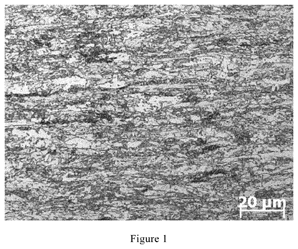
[0051]It can be seen from FIG. 1 that the steel structure manufactured by the present invention is an MA constituents+bainite+ferrite multiphase structure.

[0052]As can be seen from Table 3, the steel manufactured by the present invention has a yield strength (Rp0.2) of 620 MPa or more, a tensile strength (Rm) of 750 MPa or more, an elongation (A50) of 11% or more and a yield ratio (Rp0.2 / Rm) of 0.83 or less. More...


PUM

PropertyMeasurementUnit
elongationaaaaaaaaaa
tensile strengthaaaaaaaaaa
yield strengthaaaaaaaaaa

Abstract

Steel for coiled tubing with a low yield ratio and ultra-high strength and a preparation method thereof, wherein the chemical composition of the steel in mass percentage is: C: 0.05-0.16%, Si: 0.1-0.9%, Mn: 1.25-2.5%, P≤0.015%, S≤0.005%, Cr: 0.51-1.30%, Nb: 0.005-0.019%, V: 0.010-0.079%, Ti: 0.01-0.03%, Mo: 0.10-0.55%, Cu: 0.31-0.60%, Ni: 0.31-0.60%, Ca: 0.0010-0.0040%, Al: 0.01-0.05%, N≤0.008%, and the rest being Fe and inevitable impurity elements. The chemical composition combines the technologies of low temperature finishing rolling and low temperature coiling to obtain an MA constituent+bainite+ferrite multiphase structure. The steel has a low yield ratio and ultra-high strength with the following specific properties: yield strength≥620 MPa, tensile strength≥750 MPa, elongation≥11%, and yield ratio≤0.83, and is suitable for manufacturing coiled tubing with ultra-high strength having a grade of 110 ksi or higher.

Description

TECHNICAL FIELD[0001]The present invention relates to a steel for coiled tubing with low yield ratio and ultra-high strength and a manufacturing method thereof.BACKGROUND ART[0002]Compared with the conventional threaded connecting tubing, coiled tubing (CT) (also known as continuous tube, flexible tubing, serpentine tube or coil tube) which can be wound on a drum with a large diameter is a jointless coiled tubing formed through a miter joint of several sections of steel strips and then rolling and welding. The coiled tubing is mainly used for auxiliary operations such as well logging and completion in oilfield. With the continuous progress of the coiled tubing equipment technology in the past ten years, its application in the field of drilling has developed rapidly.[0003]The coiled tubing requires specialized equipment for operation, and has many advantages such as strong mobility, flexible operation, and reusability. However, the coiled tubing is subject to repeated deformations su...

Claims


Application Information

Patent Timeline
Patent Type & Authority Applications(United States)
IPC IPC(8): C21D9/08C21D8/10C21D6/00C22C38/58C22C38/50C22C38/48C22C38/46C22C38/44C22C38/42C22C38/02C22C38/00
CPCC21D6/004C22C38/46C22C38/58C21D6/005C21D9/08C22C38/001C21D2211/005C21D6/008C22C38/50C21D8/105C21D2211/002C22C38/004C22C38/44C22C38/42C22C38/48C22C38/02C21D8/10C22C33/04C22C38/04C22C38/06C21D8/02
Inventor ZHANG, CHUANGUOSUN, LEILEIZHENG, LEIPANG, HOUJUNLIU, JIANZHANG, YONGXU, GUODONG
Owner BAOSHAN IRON & STEEL CO LTD
Why Eureka
Try Eureka