Device for reducing pollutants in a gaseous mixture

a technology of gaseous mixture and device, which is applied in the direction of physical/chemical process catalysts, heating types, separation processes, etc., can solve the problems of significant energy consumption, low durability over time, and low efficiency of device types, so as to reduce pollutants and reduce pollutants. , the effect of high elimination efficiency

Active Publication Date: 2020-09-10
CONSORZIO COLTECH
View PDF3 Cites 4 Cited by
  • Summary
  • Abstract
  • Description
  • Claims
  • Application Information

AI Technical Summary

Benefits of technology

[0019]The aim of this invention is to provide a device for reducing pollutants in a gaseous mixture characterised by a high efficiency in terms of elimination and reduction of pollutants in a gaseous mixture and which is at the same time inexpensive and reliable in daily use.

Problems solved by technology

It follows that this type of devices has a very low efficiency, unless it is used in combination with ultraviolet lamps specifically designed and manufactured to perform the function of activating the titanium dioxide.
This also results in the fact that in order to obtain good performance levels for reducing the pollutants by means of the prior art filters it is necessary that they comprise a series of ultraviolet light sources, which are characterised by having significant energy consumptions and also low durability over time.
It is clear that on a filter device which must, by its very nature, operate continuously for the entire working day, this energy consumption is significant and problematic for the running costs of the system in which the device is installed.
Another major drawback of the ultraviolet light sources is the purchase cost and the relative low number of hours of service life, in particular if compared with the light sources in the visible spectrum of the LED type which are characterised by a very low energy consumption, a low purchase cost and at the same time a life cycle which is much greater than that of the other traditional light sources.

Method used


Image

  • Device for reducing pollutants in a gaseous mixture
  • Device for reducing pollutants in a gaseous mixture
  • Device for reducing pollutants in a gaseous mixture

Examples


Embodiment Construction

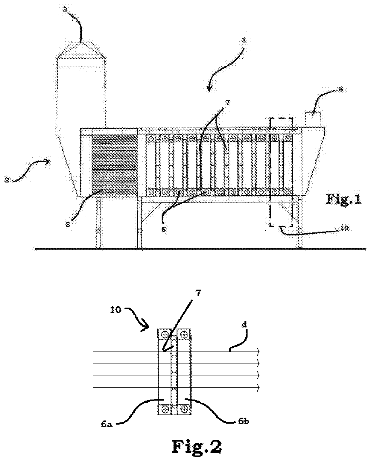
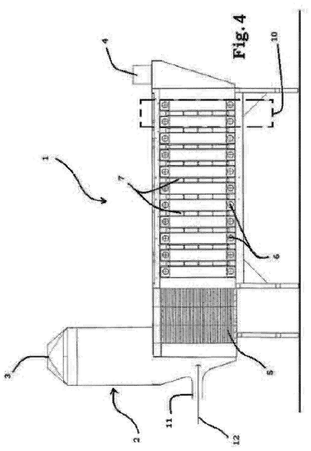
[0027]The numeral 1 in FIG. 1 denotes in general a device 1 for reducing pollutants in a gaseous mixture, for example air, which comprises a containment body 2 having an inlet portion 3 and an outlet portion 4 of the gaseous mixture.

[0028]The containment body 2 may advantageously be connected in series with the aeration ducts of the building.

[0029]The containment body 2 creates a fixed physical path imposing a fixed direction of flow, indicated for simplicity only in FIG. 2 with the letter “d”, on the gaseous mixture.

[0030]Advantageously, the containment body 2 comprises elements for resting on the ground.

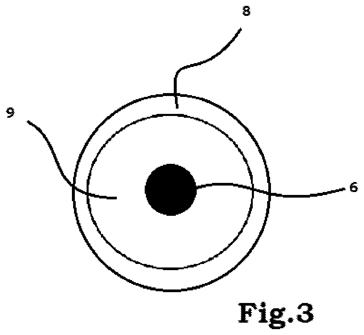
[0031]Inside the containment body there is at least one filtering unit 10, shown schematically in FIGS. 1 and 2, which comprises a photocatalytic filter 7 interposed, along the fixed direction of flow “d” between a first light source 6a and a second light source 6b both with a wavelength in the visible spectrum.

[0032]The light sources 6, 6a, 6b may be of any known type, advantageou...


PUM

PropertyMeasurementUnit
temperatureaaaaaaaaaa
wavelengthaaaaaaaaaa

Abstract

Described is a device (1) for reducing pollutants in a gaseous mixture comprising: •a containment body (2) having an inlet portion (3) for the gaseous mixture and an outlet portion (4) for the gaseous mixture, the containment body (2) imposing on the gaseous mixture a fixed direction of flow (D), •at least one filtering unit (10) comprising a photocatalytic filter (7) interposed, along the fixed direction of flow (D), between a first light source (6a) and a second light source (6b), both having a wavelength in the visible spectrum (400-700 nm), the photocatalytic filter (7) comprising a photocatalytic nanoparticle coating and the nanoparticle coating comprising titanium dioxide doped with a nitrogen doping agent. •a unit (5) for straightening the flow before the filtering unit (10).

Description

TECHNICAL FIELD[0001]This invention relates to a device for reducing pollutants in a gaseous mixture.[0002]The development and diffusion of human activities has led, over the years, to an increasingly significant increase in the pollutant substances present in the air which is breathed.[0003]More specifically, an increasing attention is dedicated to the effects which the pollutant emissions produced, for example, by production plants and means of transport have on the environment and on the ecosystems.[0004]However, many studies have shown that the level of pollutants which accumulates in a closed space can be equal, if not even greater, to that present in the outside environment.[0005]The substances most commonly present are in general nitric oxides (NOx) and comprise volatile organic compounds (VOCs), which can also have originated from commonly used household objects, such as: cleaning products, deodorants, air conditioning systems and interior decor.[0006]The need to guarantee t...

Claims


Application Information

Patent Timeline
Patent Type & Authority Applications(United States)
IPC IPC(8): A61L9/18F24F3/16B01D53/86B01J21/06B01J35/00B01J21/08B01J21/04B01J37/02F24F8/167
CPCB01J21/063B01D2255/20707B01D53/8668A61L2209/14F24F2003/1628A61L2209/12B01D53/8628B01D2255/802F24F3/1603B01J35/0013B01J21/08B01J21/04B01D2257/708B01D2257/404B01J37/0215B01J35/004A61L9/18F01N3/2086F01N3/2892F01N2510/06F01N2590/10B01D2258/06B01D2259/4508B01D2259/802Y02T10/12F24F8/167A61L2101/02A61L2101/12A61L2101/18A61L2101/24A61L2101/28A61L2209/211A61L2209/212A61L2209/22
Inventor BALDI, GIOVANNINICCOLAI, LAURABITOSSI, OLIVIABITOSSI, MARCOBONARI, SIMONE
Owner CONSORZIO COLTECH
Why Eureka
Try Eureka