System for extracting gas from tectonically-deformed coal seam in-situ by depressurizing horizontal well cavity

Active Publication Date: 2020-10-29
CHINA UNIV OF MINING & TECH +1
0 Cites 3 Cited by

AI-Extracted Technical Summary

Problems solved by technology

Tectonically-deformed coal refers to coal whose coal seam is subject to tectonic stress and whose primary structure and construction are significantly destroyed due to cracking, resulting in fractures, wrinkles, polished surfaces, and other structural changes.
Due to its hazards and difficulty in extraction and utilization, the tectonically-deformed coal is mostly discharged into the atmosphere in coal production.
Due to the extremely low permeability of tectonically-deformed coal reservoirs and the poor effect of a reconstruction method such as hydraulic fracturing, the theory of hydrophobic depressurization, desorption, and gas recovery is not suitable for tectonically-deformed coal reservoirs.
The results of exploration and development practice also show that all coal bed methane exploration and development technologies based on the theory of hydrophobic depres...

Method used

[0027]The product lifting subsystem includes a pulverization disturbance device and a hydraulic jet pump 8. The hydraulic jet pump 8 is a wide-flow jet pump, is disposed in the vertical well 7 near the bottom of the well, and is configured to lift the gas-liquid-coal mixture to a wellhead. The pulverization disturbance device is disposed between the depressurization cavity 9 and the vertical well 7 for pulverizing coal powder at the bottom of the well, so that the coal powder can be more easily lifted by the hydraulic jet pump 8 to the wellhead of the vertical well 7. In this way, fluids with coal powder concentration ≤50% are efficiently produced.
[0030]The horizontal well hole-collapse cavity-construction depressurization excitation subsystem further includes an abrasive mixing device 14. An inlet of the abrasive mixing device 14 is in communication with the liquid storage tank 3 and an abrasive tank 13, and an outlet of the abrasive mixing device 14 is in communication with the inlet of the ground power unit 15. The addition of a particular proportion of an abrasive to the excitatio...

Benefits of technology

[0017]Real-time detection and control of the operation conditions and the execution processes of the technical equipment are implemented through three layers of network architecture and software including on-site workstations, monitoring instruments and sensors, and a c...

Abstract

A system for extracting gas from a tectonically-deformed coal seam in-situ by depressurizing a horizontal well cavity is provided. A horizontal well is constructed by a horizontal well drilling and reaming subsystem and adjoins a vertical well to form a U-shaped well, and a horizontal section of the horizontal well is reamed to enlarge hole diameter. A horizontal well hole-collapse cavity-construction depressurization excitation subsystem performs pressure-pulse excitation and stress release on the horizontal well of tectonically-deformed coal bed methane, and hydraulically displaces a coal-liquid-gas mixture such that the mixture is conveyed towards a vertical well section along a depressurizing space. A product lifting subsystem further pulverizes the coal and lifts the mixture towards a wellhead of a vertical well. A gas-liquid-solid separation subsystem separates the coal, liquid and gas. A monitoring and control subsystem detects and controls the operation conditions and the execution processes of technical equipment in real time.

Application Domain

Drill bitsMining devices +9

Technology Topic

Environmental geologyTectonic deformation +11

Image

  • System for extracting gas from tectonically-deformed coal seam in-situ by depressurizing horizontal well cavity
  • System for extracting gas from tectonically-deformed coal seam in-situ by depressurizing horizontal well cavity
  • System for extracting gas from tectonically-deformed coal seam in-situ by depressurizing horizontal well cavity

Examples

  • Experimental program(1)

Example

[0023] In the figures: 1: Drill tower; 2: Pump group; 3: Liquid storage tank; 4: Coal-liquid separation device; 5: Coal-liquid-gas separation device; 6: Gas storage tank; 7: Vertical well; 8: Hydraulic jet pump; 9: Depressurization cavity; 10: Drilling tool; 10-1: Pilot assembly; 10-2: Primary and secondary reaming and retraction assembly; 10-3: Third-stage reaming and retraction assembly; 10-4: Plunger drill bit; 10-5: Blade; 10-6: Second locking mechanism; 10-7: First locking mechanism; 10-8: Drilling fluid outlet; 11: Horizontal well; 12: Coal powder collection tank; 13: Abrasive tank; 14: Abrasive mixing device; 15: Ground power unit; and 16: Underground injection device.
DETAILED DESCRIPTION OF THE EMBODIMENTS
[0024]The present invention is further described below with reference to the accompanying drawings (a left-right direction in the following description is the same as a left-right direction in FIG. 1).
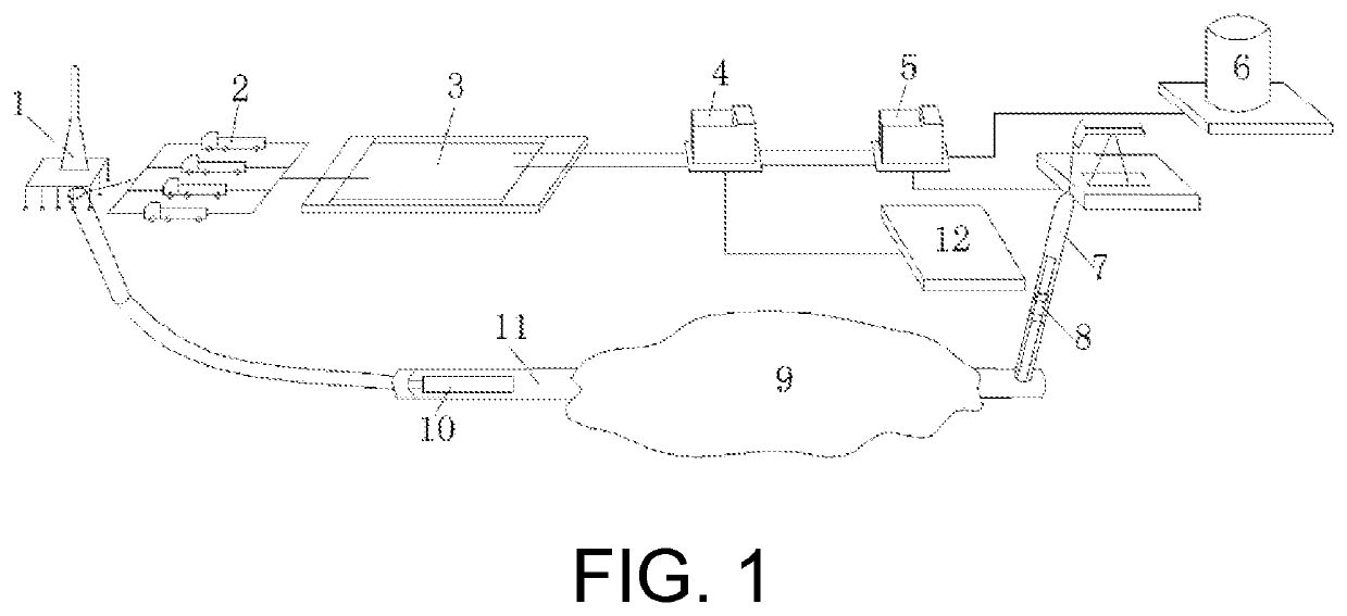
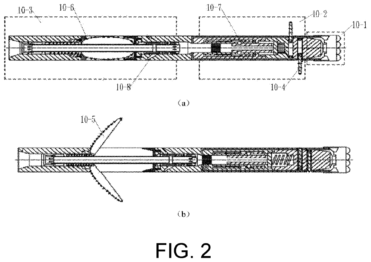
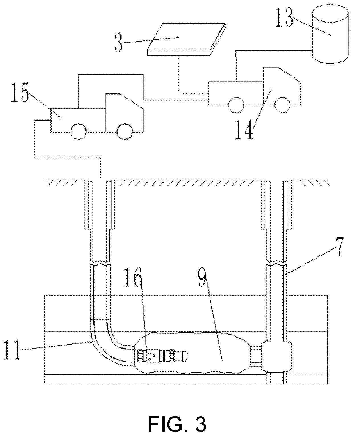
[0025]FIG. 1 to FIG. 3 show a system for extracting gas from a tectonically-deformed coal seam in-situ by depressurizing a horizontal well cavity that is used in the present invention, which includes a horizontal well drilling and reaming subsystem, a horizontal well hole-collapse cavity-construction depressurization excitation subsystem, a product lifting subsystem, a gas-liquid-solid separation subsystem, and a monitoring and control subsystem. The horizontal well drilling and reaming subsystem includes a drill tower 1, a drilling rig (not shown), a drill column string (not shown), a drilling tool 10, and a drilling fluid circulation system. Connections between the drill tower 1, the drilling rig, and the drill column string are the same as those in the prior art. The drill tower 1 is configured to place and suspend a lifting system, bear the weight of the drilling tool, store a drill pipe and a drill collar, and so on. The drilling rig is configured to power the drilling tool 10. The drill column string is a string consisting of a Kelly bar, a drill pipe, a drill collar, and another underground tool, and is configured to install the drilling tool 10. The drilling tool 10, from a connection end with the drill column string to a drilling end, includes a third-stage reaming and retraction assembly 10-3, a primary and secondary reaming and retraction assembly 10-2, and a pilot assembly 10-1 respectively. The third-stage reaming and retraction assembly 10-3 includes a plurality of expandable and closable blades 10-5 that is circumferentially disposed. The blade 10-5 is locked and positioned by a second locking mechanism 10-6. The primary and secondary reaming and retraction assembly 10-2 includes a plurality of extendable and retractable plunger drill bits 10-4 that is circumferentially disposed. The plunger drill bit 10-4 is locked and positioned by a first locking mechanism 10-7. A connection between a drilling fluid positive circulation system and another component is the same as that in the prior art. During drilling construction of a horizontal well 11, during running towards the direction of a vertical well 7, the plunger drill bit 10-4 is extended to start drilling, and during returning towards the direction of the drill tower 1, the blade 10-5 is opened. Because the diameter after the blade 10-5 is opened is greater than the diameter when the plunger drill bit 10-4 is extended, the horizontal well is reamed, thereby achieving three-stage reaming in rock mass at drillability classes I, II, III, IV and V. Three-stage reaming rates respectively reach 150%, 200%, 300%, and a diameter increase after reaming is 200% to 300%.
[0026]The horizontal well hole-collapse cavity-construction depressurization excitation subsystem includes a ground power unit 15 and an underground injection device 16. An inlet of the ground power unit 15 is in communication with a liquid storage tank 3, and an outlet of the ground power unit 15 is in communication with the underground injection device 16. The underground injection device 16 is disposed at one side of a depressurization cavity 9 in the horizontal well 11 near the drill tower 1. After completing the open-hole cavity-construction through reaming of the horizontal well 11, a booster pump in the ground power unit 15 injects high-pressure and high-speed fluids to a horizontal well cavity at a particular pulse frequency, which are sprayed by the underground injection device 16 to the depressurization cavity 9, to implement pressure-pulse excitation and stress release on the horizontal well of tectonically-deformed coal bed methane; and a gas-liquid-coal mixture is displaced through the injected high-pressure and high-speed fluids such that the mixture is conveyed towards the vertical well 7 along a depressurizing space and then produced. A depressurization excitation range (a stress release area width/a coal thickness) after the pressure-pulse excitation and the stress release are performed on the horizontal well is ≥15.
[0027]The product lifting subsystem includes a pulverization disturbance device and a hydraulic jet pump 8. The hydraulic jet pump 8 is a wide-flow jet pump, is disposed in the vertical well 7 near the bottom of the well, and is configured to lift the gas-liquid-coal mixture to a wellhead. The pulverization disturbance device is disposed between the depressurization cavity 9 and the vertical well 7 for pulverizing coal powder at the bottom of the well, so that the coal powder can be more easily lifted by the hydraulic jet pump 8 to the wellhead of the vertical well 7. In this way, fluids with coal powder concentration ≤50% are efficiently produced.
[0028]The gas-liquid-solid separation subsystem includes a coal-liquid-gas separation device 5 and a coal-liquid separation device 4. An inlet of the coal-liquid-gas separation device 5 is in communication with a wellhead pipeline of the vertical well 7, and two outlets of the coal-liquid-gas separation device 5 are in communication with a gas storage tank 6 and the coal-liquid separation device 4 respectively. Two outlets of the coal-liquid separation device 4 are in communication with a coal powder collection tank 12 and the liquid storage tank 3 respectively. The subsystem can achieve gas-liquid-coal mixture pre-treating, gas separation, liquid-coal separation, coal-gas collection, excitation liquid (or water) purification and recycling, with gas separation efficiency of above 90% to 95%, excitation liquid separation and collection efficiency of above 80% to 90%, and a coal powder collection capability of above 98%. The main function is to achieve preliminary separation of gas, liquid, and coal powder through the coal-liquid-gas separation device 5 and the coal-liquid separation device 4. The separated coal and gas respectively enter the coal powder collection tank 12 and the gas storage tank 6 for storage, and the treated excitation liquid enters the liquid storage tank 3 for recycling, to ensure continuous extraction.
[0029]The monitoring and control subsystem includes three layers of network architecture and software including on-site workstations, monitoring instruments and sensors, and a central server control system. Based on a high-precision sensor technology, through construction of the three layers of network architecture including the sensors, the on-site workstations, and the central server control system, and application of configuration analysis software and an Internet of Things perception technology, a data acquisition and monitoring system that is “accurate, visual, interactive, fast, and intelligent” is formed to detect and control the operation conditions and the execution processes of technical equipment in real time, so as to collect, display, process, and analyze engineering data.
[0030]The horizontal well hole-collapse cavity-construction depressurization excitation subsystem further includes an abrasive mixing device 14. An inlet of the abrasive mixing device 14 is in communication with the liquid storage tank 3 and an abrasive tank 13, and an outlet of the abrasive mixing device 14 is in communication with the inlet of the ground power unit 15. The addition of a particular proportion of an abrasive to the excitation liquid improves the capability of the excitation liquid to cut a coal rock, thereby improving extraction efficiency.
[0031]The blade 10-5 on the drilling tool 10 is rotated and opened towards the direction of the drill tower 1. A drilling fluid outlet 10-8 is disposed on the right of the blade 10-5, and gradually inclines towards the direction of the blade 10-5 when extending towards the outer circumference of the drilling tool 10 from an inner cavity of the drilling tool 10. During drilling, drilling fluids can achieve cooling and auxiliary cutting functions like conventional drilling fluids, and can also provide sufficient support for the expansion of the blade 10-5, to reduce rigid deformation of a connecting member with the blade 10-5, and prolong a service life of the device.
[0032]Pumps in the extraction system are all integrated in a pump group 2 except for the hydraulic jet pump 8, which is convenient for communication with the liquid storage tank 3 and underground equipment pipelines, thereby reducing the complexity of connections between the devices in the extraction system.
[0033]A method of extracting gas from a tectonically-deformed coal seam in-situ by depressurizing a horizontal well cavity includes the following steps:
[0034]1) arranging various devices on the ground and connecting the corresponding devices, and using an existing drilling device and processing technology to construct vertical well sections and kick-off sections of a vertical well 7 and a horizontal well 11 to a target coal seam, where a drilling fluid circulation pump in a pump group 2 provides drilling fluids for the underground during construction;
[0035]2) replacing a drilling tool with a drilling tool 10 and lowering the drilling tool 10 to the kick-off section of the underground horizontal well, performing three-stage reaming and large-diameter well completion on a loose tectonically-deformed coal seam, and forming a horizontal well section that runs through the vertical well 7 (forming a U-shaped well in which the horizontal well adjoins the vertical well), to complete the open-hole cavity-construction, where the drilling fluid circulation pump in the pump group 2 provides the drilling fluids for the underground during construction;
[0036]3) removing all drilling tools from the well, lowering an underground injection device 16 to a starting point of the horizontal section of the horizontal well 11, lowering gas-liquid-coal mixture lifting and production devices, namely, a pulverization disturbance device and a hydraulic jet pump 8 to the vertical well 7, and connecting a wellhead of the vertical well 7 to a coal-liquid-gas separation device 5;
[0037]4) starting a ground power unit 15, namely, a high-pressure pulse pump in the pump group 2, injecting high-pressure and high-speed fluids into the horizontal section of the horizontal well 11 at a specified frequency, to cut and pulverize a coal rock and implement pressure-pulse excitation and stress release on the horizontal section of the horizontal well 11 to form a depressurization cavity 9, then accelerating water into high-velocity jet flows, to further pulverize and flush coal powder, and conveying a formed gas-liquid-coal mixture to the bottom of the vertical well 7, where during the pressure-pulse excitation and the stress release on the horizontal section of the horizontal well 11, an abrasive mixing device 14 may be connected between a liquid storage tank 3 and the underground injection device 16, and through combined action of a high-pressure mud pump and the high-pressure pulse pump in the pump group 2, an excitation liquid containing an abrasive is injected into the underground, to improve the capability of the excitation liquid to cut a coal rock, thereby improving extraction efficiency;
[0038]5) starting the underground pulverization disturbance device and the hydraulic jet pump 8, further pulverizing the coal powder that flows into the bottom of the vertical well 7, and then lifting the coal powder to the ground to enter the coal-liquid-gas separation device 5; and
[0039]6) pre-treating the mixture that enters the coal-liquid-gas separation device 5, to enable a coal-liquid mixture and coal bed methane that are separated to respectively enter a coal-liquid separation device 4 and a gas storage tank 6, further treating the coal-liquid mixture that enters the coal-liquid separation device 4, and storing coal powder and a liquid that are separated in a coal powder collection tank 12 and the liquid storage tank 3 respectively.
[0040]In step 6), the separated liquid is purified before entering the liquid storage tank 3 to ensure efficient recycling in production.

PUM

no PUM

Description & Claims & Application Information

We can also present the details of the Description, Claims and Application information to help users get a comprehensive understanding of the technical details of the patent, such as background art, summary of invention, brief description of drawings, description of embodiments, and other original content. On the other hand, users can also determine the specific scope of protection of the technology through the list of claims; as well as understand the changes in the life cycle of the technology with the presentation of the patent timeline. Login to view more.

Similar technology patents

Method and Apparatus for Blind Signal Extraction

ActiveUS20130156222A1efficiently extract
Owner:KOREA ADVANCED INST OF SCI & TECH

Novel diglycosidase and gene encoding the same

ActiveUS20100221810A1efficiently extractproduct be use
Owner:AMANO ENZYME INC

Hydroelectric power plant and method of generating power

InactiveUS20070217901A1efficiently extract
Owner:HYDRO INNOVATION CORP

Folding Tube

InactiveUS20100084427A1efficiently extract
Owner:KARDACH GERALD E

Classification and recommendation of technical efficacy words

  • efficiently extract

Light emitting system with high extraction efficency

ActiveUS20050173717A1efficiently extract
Owner:DICON FIBEROPTICS

Display element

InactiveUS20140368766A1efficiently extract
Owner:SHARP KK

Optical Device Structure

ActiveUS20080284320A1efficiently extract
Owner:BRAGGONE

Characteristic image extraction method and ophthalmologic apparatus

ActiveUS20110267580A1alleviate inefficiencyefficiently extract
Owner:CANON KK

LED device and coating liquid used for production of same

InactiveUS20150353740A1efficiently extractless degradation
Owner:KONICA MINOLTA INC
Why Eureka
Try Eureka