Eureka AIR delivers breakthrough ideas for toughest innovation challenges, trusted by R&D personnel around the world.

Exhaust catalyst light-off in an opposed-piston engine

Active Publication Date: 2020-11-05
ACHATES POWERS INC
View PDF0 Cites 1 Cited by
  • Summary
  • Abstract
  • Description
  • Claims
  • Application Information

AI Technical Summary

Benefits of technology

The patent describes a method for controlling a two-stroke engine during a transition period where the engine is operating at a low load. This method involves reducing the amount of air and fuel going into the engine and advancing the timing of fuel injection. This helps to quickly reach the desired temperature for optimum engine performance.

Problems solved by technology

During the period in which the engine starts until its exhaust enthalpy rises to a level that causes catalyst light-off, an SCR system will not be effective at reducing the engine-out NOx.
A low value of the modified air delivery ratio results in a higher level of internal residuals, thereby leading to an increase in trapped temperature.
The exhaust control strategy for an opposed-piston described in PCT international publication WO 2013 / 126347 is based on trapped temperature in a cylinder, and may, in some cases, be incomplete, if not inaccurate, for failing to account for heat loss during transport of the exhaust gas from the cylinder to an aftertreatment device.

Method used


Image

  • Exhaust catalyst light-off in an opposed-piston engine
  • Exhaust catalyst light-off in an opposed-piston engine
  • Exhaust catalyst light-off in an opposed-piston engine

Examples


first embodiment

[0048]A first embodiment of a catalyst light-off method of controlling the opposed-piston engine 8 may be understood with reference to FIGS. 4 and 5. When an engine start signal 112 is input to start the engine (step S1), the ECU 94 generates a Crank signal to activate the starter motor device 110, which commences to crank the opposed-piston engine 8. While cranking continues, the ECU 94 may execute a cold start procedure to quickly initiate and stabilize combustion. At the transition to run mode control, engine operation enters a stable idling state. During this initial period, the ECU 94 reads various sensors to determine engine speed and engine load, and reads the exhaust gas temperature sensor 102 to determine whether a catalyst light-off control mode should be activated. An engine state check can also be executed by the ECU 94 using the engine speed sensor 97 to detect when the engine control transitions out of the crank mode (step S2). When the crank mode is completed, the ECU...

second embodiment

[0053]A second embodiment of a catalyst light-off mode of controlling the opposed-piston engine 8 may be understood with reference to FIGS. 4 and 6. In this embodiment, the ECU 94 may determine, by one or more of estimation, calculation, and table look-up, a value of exhaust enthalpy based on a catalyst temperature value indicative of a temperature of the catalyst in the SCR 105 and an exhaust mass flow rate value indicative of a mass flow rate of exhaust gas in the exhaust passage 49.

[0054]In the second embodiment, a catalyst temperature (TCAT) is determined, calculated, or estimated by the ECU 94 on the basis of a difference between the inlet temperature (TCat-in) of the catalytic device and an outlet temperature (TCat-out) of the catalytic device, and, possibly, other parameters. This embodiment may be implemented by an exhaust gas temperature sensor arrangement including the first exhaust gas temperature sensor 102 to detect TCat-in and a second exhaust temperature sensor 103 lo...


PUM


Abstract

In an opposed-piston engine which includes a catalytic aftertreatment device in its exhaust system an exhaust gas condition indicating a catalyst temperature of the aftertreatment device is monitored. When the catalyst temperature is near or below a light-off temperature, a catalyst light-off procedure is executed to elevate the temperature of the catalyst.

Description

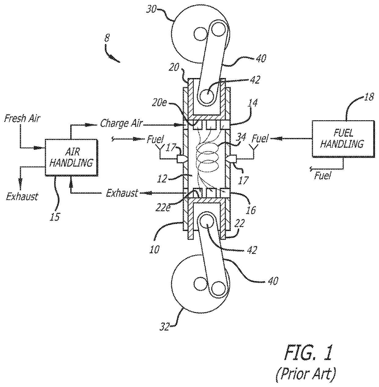
TECHNICAL FIELD[0001]The invention concerns catalyst light-off in an opposed-piston engine operated by compression-ignited combustion of an air / fuel mixture.BACKGROUND[0002]An opposed-piston engine is an internal combustion engine characterized by an arrangement of two pistons disposed in the bore of a cylinder for reciprocating movement in opposing directions along the central axis of the cylinder. In many cases, an opposed-piston engine completes a cycle of operation with a single complete rotation of a crankshaft and two strokes of a piston connected to the crankshaft. The strokes are typically denoted as compression and power strokes. Each piston moves between a bottom center (BC) region where it is nearest one end of the cylinder and a top center (TC) region within the cylinder where it is furthest from the one end and closest to the other piston. During a compression stroke, the pistons move away from BC positions, toward each other, compressing charge air between their end su...

Claims


Application Information

Patent Timeline
IPC IPC(8): F02D41/02F02B75/28F02D41/00F02B37/24F02B37/18F02D41/40F02B25/08F01N11/00
CPCF02B25/08F02B37/18F02D41/0255F02D2041/389F02D41/401F01N11/00F02B37/24F02B75/282F02D41/0245F02D41/0007F01N3/035F01N3/103F01N3/2013F01N3/2086F02B37/04F02B37/12F02B39/04F02D41/1441F02D41/1446F02D41/40F02D9/04F01N2900/1602F02D2200/0804F02D2400/04F02D41/005F02D41/08F02D41/107F02D41/3836F01B7/14F01N3/2066
Inventor GHAZI, AHMADSCHUM, DANIEL M.REDON, FABIEN G.PATIL, SAMRAT M.
Owner ACHATES POWERS INC
Why Eureka
Eureka Blog
Learn More