Optical filter and Infrared Image Sensing System Including the Same

an infrared image and filter technology, applied in the field of optical sensing, can solve the problems of poor anti-reflection effect of the near-infrared light and cut-off effect of the optical filter in the related art, and poor adhesion of the film layer, so as to improve the accuracy of final face recognition and gesture recognition, the effect of ensuring a high transmittance of near-infrared ligh

Pending Publication Date: 2020-12-17
XINYANG SUNNY OPTICAL CO LTD
View PDF18 Cites 2 Cited by
  • Summary
  • Abstract
  • Description
  • Claims
  • Application Information

AI Technical Summary

Benefits of technology

[0007]The object of the present disclosure is to provide an optical filter and an infrared image sensing system including the optical filter, which solve the problems of poor anti-reflection effect on near-infrared light and poor adhesion of film layer in existing optical filters.
[0025]According to a solution of the present disclosure, in a case that the IR film layer and the AR film layer are disposed in the manner described above, at the same time of effectively ensuring a high transmittance of near-infrared light, a shift amount of the central wavelength of the passband of the optical filter with angle can be controlled below 20 nm. In addition, since third refractive-index-material layers M are disposed in the IR film layer and the AR film layer and arranged according to the manner described above, the total thickness of the film layers of the optical filter of the present disclosure is effectively reduced, and at the same time, adhesion of the film layers can be improved.
[0026]According to a solution of the present disclosure, the present disclosure provides an infrared image sensing system including the optical filter of the present disclosure. Since the optical filter of the present disclosure is provided, near-infrared light can be anti-reflected and light in other wave bands can be cut off when shooting, thereby improving the accuracy of final face recognition and gesture recognition.

Problems solved by technology

However, the anti-reflection effect on near-infrared light and the cut-off effect on visible light of the optical filter in the related art are poor.
At the same time, there are problems that the thickness of film layer in the film system is thick and the adhesion of the film layer is poor.
As such, when the optical filter is assembled into devices such as for face recognition and gesture recognition, the imaging effect is poor and the recognition accuracy is not high.
Therefore, a heretofore unaddressed need exists in the art to address the aforementioned deficiencies and inadequacies.

Method used


Image

  • Optical filter and Infrared Image Sensing System Including the Same
  • Optical filter and Infrared Image Sensing System Including the Same
  • Optical filter and Infrared Image Sensing System Including the Same

Examples


example 1

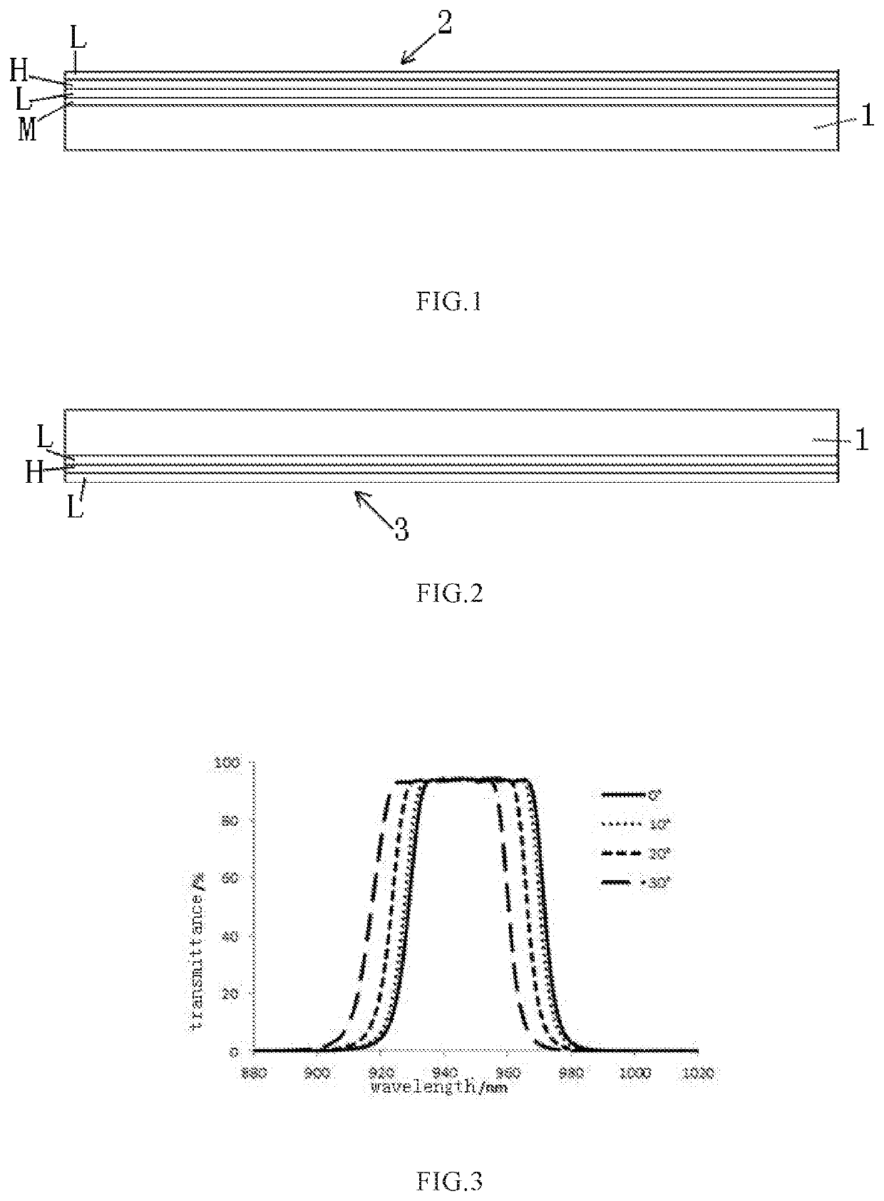
[0053]In this embodiment, when viewed in a direction away from the glass substrate 1, the structure of the IR film layer 2 of the optical filter is M, (LH)*n, L, wherein optical thicknesses of the second refractive-index-material layer H, the third refractive-index-material layer M and the first refractive-index-material layer L are one fourth of a reference wavelength respectively, a physical thickness of the second refractive-index-material layer H and a physical thickness of the first refractive-index-material layer L satisfy a relationship: 0.05≤DL / DH≤20 and a physical thickness of the third refractive-index-material layer M and the physical thickness of the second refractive-index-material layer H satisfy the relationship: 0.02≤DM / DH≤50. n=11, and a total thickness of the IR film layer 2 is 3.41 μm. When viewed in a direction away from the glass substrate 1, the structure of the AR film layer 3 is (LH)*q, L, wherein q=12. The physical thickness of the second refractive-index-ma...

example 2

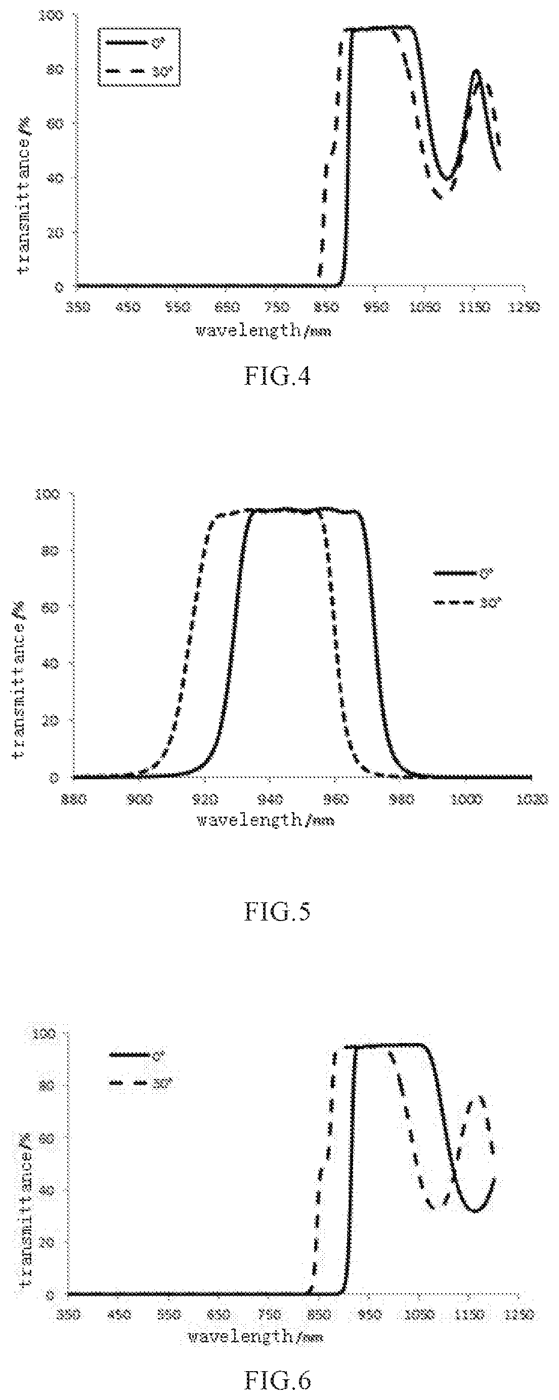
[0061]In this embodiment, when viewed in a direction away from the glass substrate 1, the structure of the IR film layer 2 of the optical filter is (LH)*s, L, M, (LH)*p, L, wherein optical thicknesses of the second refractive-index-material layer H, the third refractive-index-material layer M and the first refractive-index-material layer L are one fourth of a reference wavelength respectively, a physical thickness of the second refractive-index-material layer H and a physical thickness of the first refractive-index-material layer L satisfy a relationship: 0.05≤DL / DH≤20 and a physical thickness of the third refractive-index-material layer M and the physical thickness of the second refractive-index-material layer H satisfy the relationship: 0.02 DM / DH≤50. s=5, p=6, and a total thickness of the IR film layer 2 is 3.2 μm. When viewed in a direction away from the glass substrate 1, the structure of the AR film layer 3 is (LH)*q, L, wherein q=12. The physical thickness of the second refra...

example 3

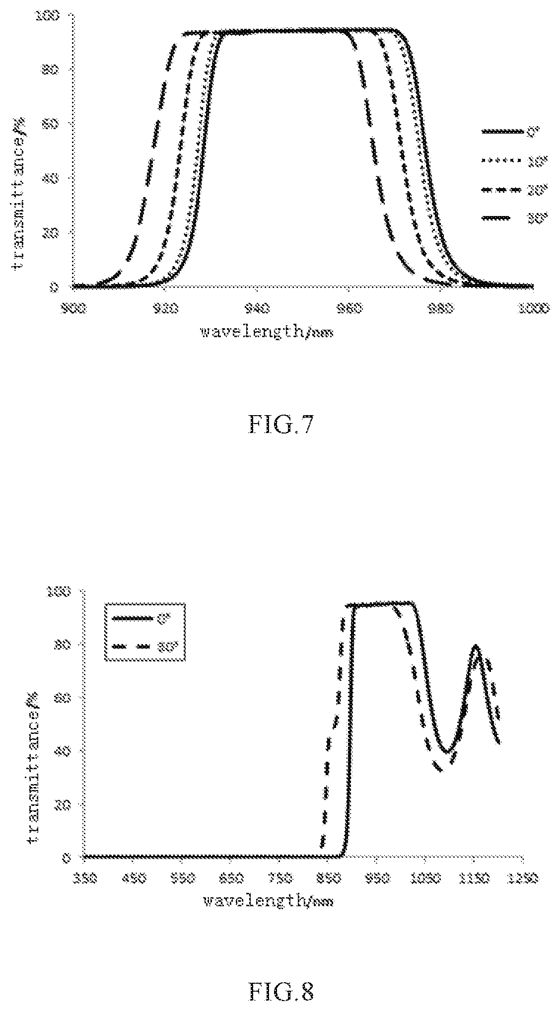
[0068]In this embodiment, when viewed in a direction away from the glass substrate 1, the structure of the IR film layer 2 of the optical filter is M, (LH)*n, L, wherein optical thicknesses of the second refractive-index-material layer H, the third refractive-index-material layer M and the first refractive-index-material layer L are one fourth of a reference wavelength respectively, a physical thickness of the second refractive-index-material layer H and a physical thickness of the first refractive-index-material layer L satisfy a relationship: 0.05≤DL / DH≤20, and a physical thickness of the third refractive-index-material layer M and the physical thickness of the second refractive-index-material layer H satisfy the relationship: 0.02≤DM / DH≤50. n=11, a total thickness of the IR film layer 2 is 4.64 μm. When viewed in a direction away from the glass substrate 1, the structure of the AR film layer 3 is (LH)*q, L, wherein q=12. The physical thickness of the second refractive-index-mater...


PUM

PropertyMeasurementUnit
wavelength rangeaaaaaaaaaa
refractive indexaaaaaaaaaa

Abstract

The present disclosure relates to an optical filter and an infrared image sensing system including the optical filter. The optical filter includes a glass substrate, and an IR film layer and an AR film layer plated on two opposite surfaces of the glass substrate; the IR film layer includes a first refractive-index-material layer, a second refractive-index-material layer, and a third refractive-index-material layer; the refractive index of the third refractive-index-material layer is greater than the refractive index of the first refractive-index-material layer, and the refractive index of the second refractive-index-material layer is greater than the refractive index of the third refractive-index-material layer. The optical filter of the present disclosure has a good anti-reflection effect on near-infrared light so that a high accuracy of face recognition and gesture recognition is ensured.

Description

CROSS-REFERENCE TO RELATED PATENT APPLICATION[0001]This application is a national stage application of PCT Application No. PCT / CN2019 / 077849. This Application claims priority from PCT Application No. PCT / CN2019 / 077849 filed Mar. 12, 2019, CN Application No. CN 201810884048.1 filed Aug. 6, 2018, the contents of which are incorporated herein in the entirety by reference.[0002]Some references, which may include patents, patent applications, and various publications, are cited and discussed in the description of the present disclosure. The citation and / or discussion of such references is provided merely to clarify the description of the present disclosure and is not an admission that any such reference is “prior art” to the present disclosure described herein. All references cited and discussed in this specification are incorporated herein by reference in their entireties and to the same extent as if each reference was individually incorporated by reference.FIELD OF THE INVENTION[0003]T...

Claims


Application Information

Patent Timeline
Patent Type & Authority Applications(United States)
IPC IPC(8): G02B5/20G02B1/115C03C17/34H04N5/33
CPCC03C2217/734C03C17/3482G02B1/115C03C2218/155C03C2217/214C03C2217/213H04N5/33G02B5/208G02B5/281G02B5/285G02B5/288
Inventor CHEN, CEDING, WEIHONGXIAO, NIANGONGCHEN, JIII
Owner XINYANG SUNNY OPTICAL CO LTD
Why Eureka
Try Eureka