Eureka AIR delivers breakthrough ideas for toughest innovation challenges, trusted by R&D personnel around the world.

Storage integrated heat exchanger

a heat exchanger and heat exchanger technology, applied in indirect heat exchangers, lighting and heating apparatuses, laminated elements, etc., can solve the problems of loss of user comfort, delay in heat delivery, and inoptimisation of heat exchangers, so as to improve the thermal contact

Active Publication Date: 2020-12-24
VLAAMSE INSTELLING VOOR TECHNOLOGISCH ONDERZOEK NV VITO
View PDF0 Cites 4 Cited by
  • Summary
  • Abstract
  • Description
  • Claims
  • Application Information

AI Technical Summary

Benefits of technology

The invention relates to a system for efficient heat storage and management. It uses three or more different phase change materials (PCMs) separated by a sealant, which allows for independent control of charging and discharging. The system can be fed with gas or liquid, such as water, which makes the system easier to use. The grading of the PCMs can improve the charging and discharging of the heat exchanger. The technical effects of this system include improved efficiency and control over heat energy storage and management.

Problems solved by technology

Heat exchangers which exploits a phase changing material in heat recovery and release have previously been described, but such heat exchangers have not been optimised for example in accelerating the start-up phase of exchanger heat exchanger with a counter current flow of the heat exchanging media.
In other, more general applications, the down-time and the resulting temperature drop results in loss of user comfort.
When put back into operation, there is a delay in the delivery of heat as first the internal structure must be reheated to the operational temperature gradient across the heat exchanger.
Both scenario's result in loss of comfort.
In domestic appliances, like dishwashers and washing machines, there is a mismatch between the need for heating and the availability of waste heat.

Method used


Image

  • Storage integrated heat exchanger
  • Storage integrated heat exchanger
  • Storage integrated heat exchanger

Examples


case 1

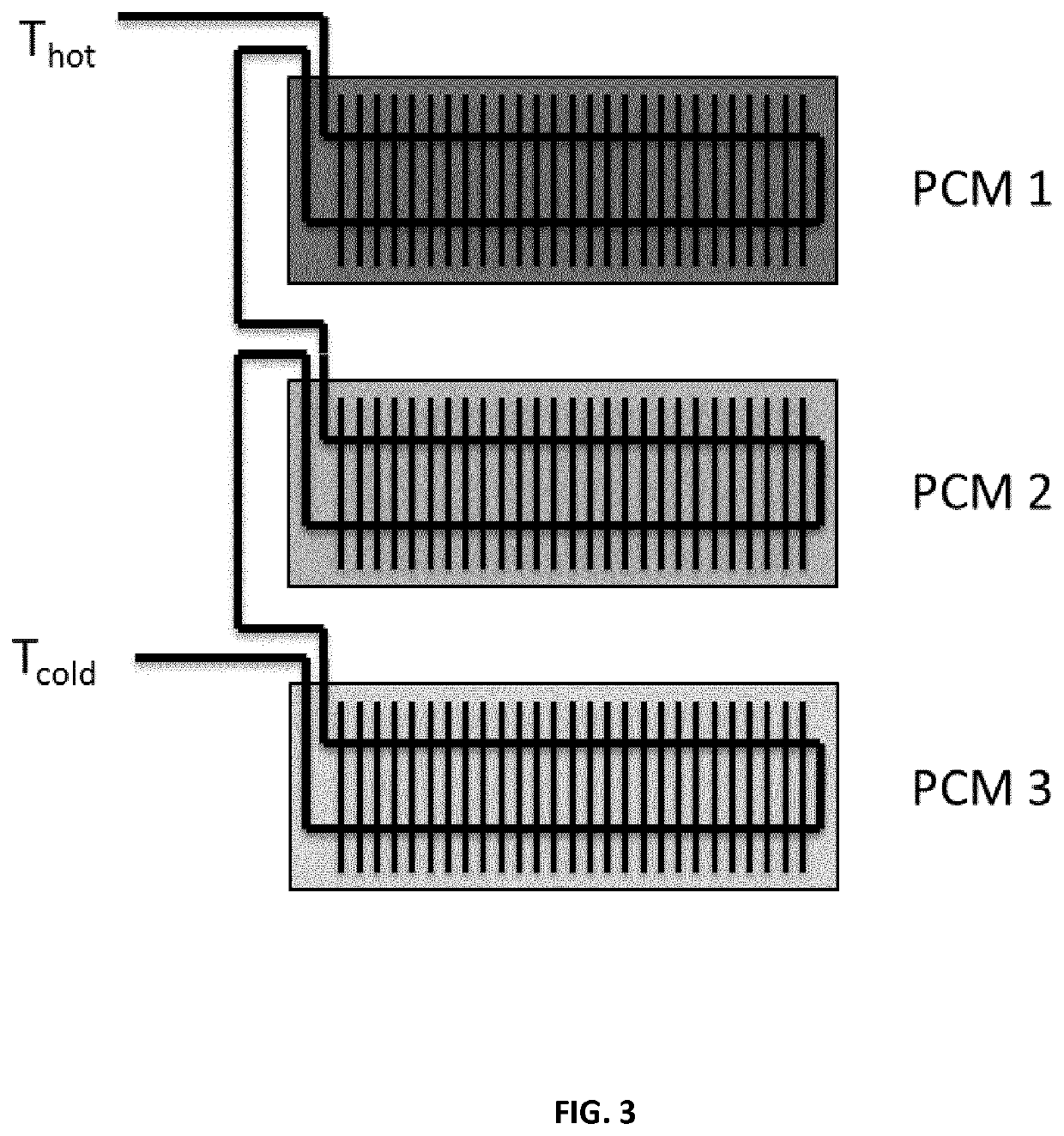
[0122] store heat in 1 PCM with a melting temperature of 20° C. (between 60° C. and 10° C.). The waste heat stream can in theory be cooled till a temperature of 20° C. The cold stream can in the next cycle be heated (in theory) to a temperature of 20° C. There is however an imbalance between heat stored and heat that can be used. Theoretically, 20% of the waste heat stream can be reused to preheat the cold stream.

case 2

[0123] store heat in 1 PCM with a melting temperature of 50° C. (between 60° C. and 10° C.). The waste heat stream can in theory be cooled till a temperature of 50° C. The cold stream can be heated (in theory) in the next cycle till a temperature of 50° C. But due to the fact that the waste heat stream can only be cooled till a temperature 50° C., 80% of the waste heat is not stored. Theoretically, only 20% of the waste heat stream can be reused to preheat the cold stream.

case 3

[0124] store heat in 1 PCM with a melting temperature of 35° C. (between 60° C. and 10° C.). The waste heat stream can in theory be cooled till a temperature of 35° C. The cold stream can in the next cycle be heated (in theory) till a temperature of 35° C. Theoretically, 50% of the waste heat stream can be reused to preheat the cold stream.


PUM


Abstract

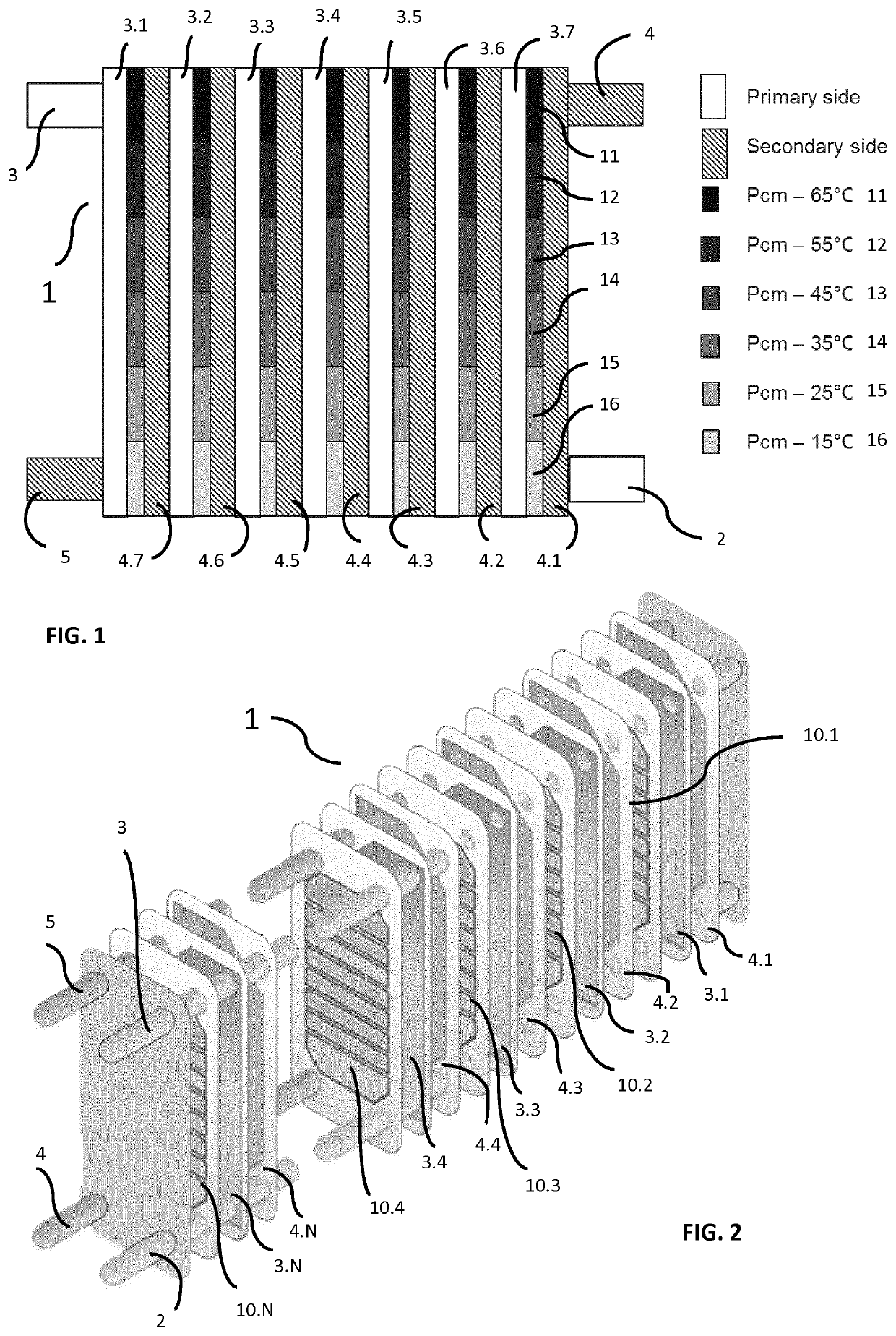
A heat exchanger with integrated thermal storage, for example, having a new tertiary side utilising phase change material in between and in thermal contact with the primary and secondary circuits, e.g. of a plate heat exchanger. The tertiary side helps reduce e.g. leak flows in district heating applications, or reduce energy losses in periods of low flow through the heat exchanger. By including thermal energy storage in a heat exchanger or reactor, response times of the systems are reduced as well as internal energy losses, and external energy storage units are reduced in number or are potentially rendered obsolete.

Description

[0001]The present invention relates to heat exchangers and reactors with heat exchange that make use of phase change materials as well as methods of operating them.BACKGROUND[0002]Traditionally, heat exchangers consist of a series of metal plates that distribute heat originating from a primary circuit to a secondary circuit. Thermal energy storage solutions are used as a component separate from the heating systems, and not integrated as part of the heat exchanger itself.[0003]Heat exchangers which exploits a phase changing material in heat recovery and release have previously been described, but such heat exchangers have not been optimised for example in accelerating the start-up phase of exchanger heat exchanger with a counter current flow of the heat exchanging media.[0004]In district heating substations, (plate) heat exchangers can have an internal volume of heat carrying medium. When used, a constant flow can maintain the internal temperature gradient of the heat exchanger. Duri...

Claims


Application Information

Patent Timeline
Patent Type & Authority Applications(United States)
IPC IPC(8): F28D20/02F28D21/00
CPCF28D21/0012F28D20/026F28D2020/0082F28F3/02F28D9/005F28D9/0093F28D20/021F28D2020/0008F28D2020/0013Y02E60/14F28D20/02
Inventor VAN BAEL, JOHANSALENBIEN, ROBBE
Owner VLAAMSE INSTELLING VOOR TECHNOLOGISCH ONDERZOEK NV VITO
Why Eureka
Eureka Blog
Learn More