Biomimetic plywood motifs for bone tissue engineering

a biomimetic plywood and bone tissue technology, applied in the field of lamellar structures with multiple levels, can solve the problems of high invasiveness, high risk of complications, and the geometric organization of most fabricated scaffold designs remains relatively unsophisticated in terms of mechanical and potential physiological performance and its relationship to the structur

Active Publication Date: 2021-01-07
UNIVERSITY OF PITTSBURGH
View PDF0 Cites 5 Cited by
  • Summary
  • Abstract
  • Description
  • Claims
  • Application Information

AI Technical Summary

Benefits of technology

[0019]Further, the additive process can be selected from conventional solid free-form and layered manufacturing processes, such as, 3-D printing, as well as, fused deposition modeling (FDM), laser beam and electron beam processes. The 3-D printing process can include use of a binder-jet-3-DP apparatus.

Problems solved by technology

While fulfilling criteria of osteoconductivity (surface biocompatibility for growth of bone tissue) and osteoinductivity (recruitment and stimulation of immature cells into preosteoblasts), these methods have associated therewith risks of complications and they are highly invasive.
Thus, the treatment of large-scale bone defects and the development of sophisticated synthetic tissue substitutes are currently major issues aggressively researched in the field of bone tissue engineering.
Similarly, bioceramic polymer and polymer composite scaffolds have also been explored for understanding structure-performance relationships, but most fabricated scaffold designs remain relatively unsophisticated in terms of geometric organization and its relationship to both mechanical and potential physiological performance.
Although past research has been successful in demonstrating significant differences in mechanical performance in relation to scaffold design, replication of complex behaviors of native tissue through biomimetic design is a direction requiring further consideration and effort.

Method used


Image

  • Biomimetic plywood motifs for bone tissue engineering
  • Biomimetic plywood motifs for bone tissue engineering
  • Biomimetic plywood motifs for bone tissue engineering

Examples


examples

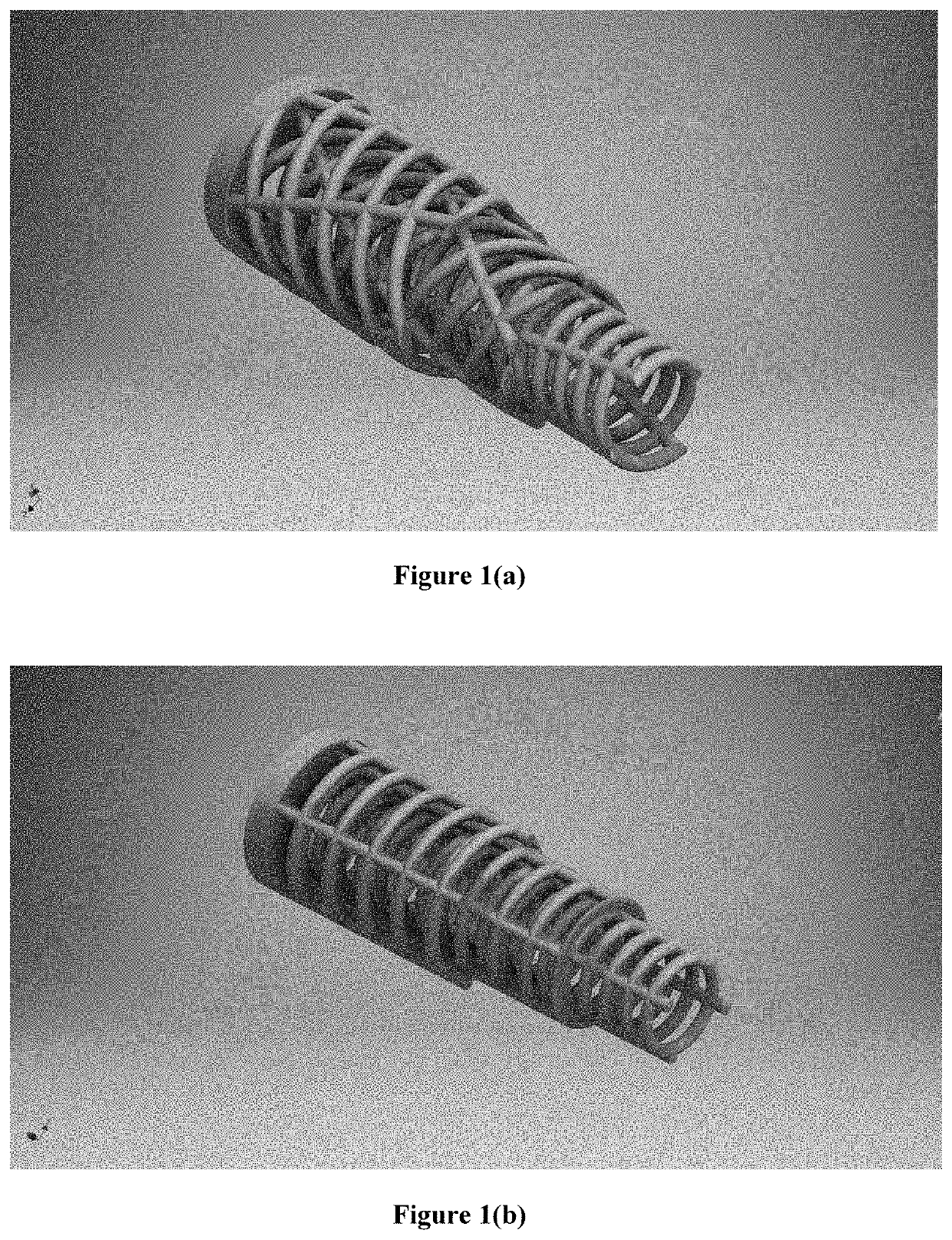
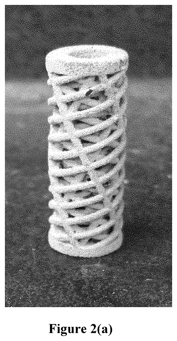
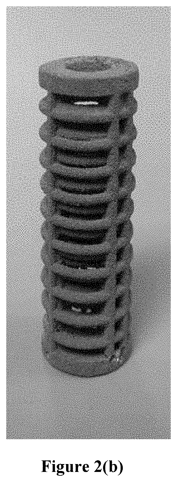
[0046]The merits of a biomimetic scaffold design in accordance with the invention were compared with conventional mesh scaffold designs. Scaffolds were characterized under uniaxial compression testing, followed by scanning electron microscopy and micro-computer tomography analyses. Observation and connection of failure defects at the microstructural level to overall bulk scaffold mode of failure, led to the conclusions that utilizing a biomimetic lamellar plywood design improved scaffold performance similarly to native tissue by, not only, improving mechanical performance, but also mode of failure in more complex, hierarchical behaviors such as the mode of crushing and fracture propagation.

[0047]Mechanical performance of similar fiber-reinforced composite materials was previously evaluated through analysis of stress-strain performance, crushing modes, and their associated crushing mechanisms which contribute to the overall structural failure under compressive loading. Although ply o...


PUM

PropertyMeasurementUnit
angular rotationaaaaaaaaaa
thicknessaaaaaaaaaa
particle sizeaaaaaaaaaa

Abstract

The invention relates generally to generation of biomimetic scaffolds for bone tissue engineering and, more particularly, to multi-level lamellar structures having rotated or alternated plywood designs to mimic natural bone tissue. The invention also includes methods of preparing and applying the scaffolds to treat bone tissue defects. The biomimetic scaffold includes a lamellar structure having multiple lamellae and each lamella has a plurality of layers stacked parallel to one another. The lamellae and/or the plurality of layers is rotated at varying angles based on the design parameters from specific tissue structural imaging data of natural bone tissue, to achieve an overall trend in orientation to mimic the rotated lamellar plywood structure of the naturally occurring bone tissue.

Description

CROSS-REFERENCE TO RELATED APPLICATIONS[0001]This application is a continuation-in-part application, which claims the priority of and benefit from U.S. Ser. No. 16 / 099,459 entitled “BIOMIMETIC PLYWOOD MOTIFS FOR BONE TISSUE ENGINEERING,” filed on Nov. 7, 2018, which is a U.S. National Stage Application under 35 U.S.C. § 371 of PCT International Application No. PCT / US2017 / 033480, entitled “BIOMIMETIC PLYWOOD MOTIFS FOR BONE TISSUE ENGINEERING,” filed on May 19, 2017, which claims priority under 35 U.S.C. § 119(e) from U.S. provisional patent application No. 62 / 338,790, entitled “BIOMIMETIC ROTATED LAMELLAR PLYWOOD MOTIFS OF METAL ALLOY SCAFFOLDS BY ADDITIVE MANUFACTURING FOR BONE TISSUE ENGINEERING,” filed on May 19, 2016, the contents of which are incorporated herein by reference.GOVERNMENT SUPPORT[0002]This invention was made with government support under GM008208 awarded by the National Institutes of Health (NIH) and FA8650-12-2-7230 awarded by the Air Force Research Laboratory (A...

Claims


Application Information

Patent Timeline
Patent Type & Authority Applications(United States)
IPC IPC(8): A61F2/28A61F2/30B33Y10/00B33Y80/00
CPCA61F2/28B29C64/165B33Y10/00B33Y80/00A61F2002/30224A61F2002/2835A61F2002/30985A61F2002/30973A61F2002/30062A61F2310/00017A61F2310/00029A61F2310/00023A61F2310/00041A61F2310/00293A61F2310/00005A61F2/3094A61F2002/30118A61F2002/30289A61F2002/3092A61F2002/30952A61F2002/30971A61F2/30771
Inventor KUMTA, PRASHANT N.YU, GARYROY, ABHIJIT
Owner UNIVERSITY OF PITTSBURGH
Why Eureka
Try Eureka