
Carbon Nanocomposite Sensors

a carbon nano-composite and sensor technology, applied in the field of piezoresistive sensors, can solve the problems of difficult use of many conventional pressure sensors in these applications, and many limitations of laboratory-based systems for monitoring human motion

Pending Publication Date: 2021-01-07
UNIVERSITY OF DELAWARE
View PDF2 Cites 7 Cited by
  • Summary
  • Abstract
  • Description
  • Claims
  • Application Information

AI Technical Summary

Benefits of technology

The invention is about a pressure sensor that can be made from a fabric made of woven or nonwoven fibers coated with carbon nanotubes. This sensor can be integrated into footwear or clothing to monitor and analyze human activity during daily living.

Problems solved by technology

Space constraints and weight limitations make the use of many conventional pressure sensors difficult for these applications.
Although these techniques are commonly used in a research environment, there are many limitations of utilizing laboratory-based systems for monitoring human motion.
Aside from being expensive, the laboratory conditions are very different from daily home / work environments, and patients are not monitored during their day-to-day activities.
Additionally, patients can only be monitored for a limited amount of time.
Furthermore, the instrumentation using markers and data analysis is complex.
While metallic coatings give promising results, the coatings increase the stiffness of the fabric making it less comfortable.
Additionally, the metallic coating often cracks under high deformation and can be prone to corrosion.
While these techniques are well established and highly effective in the analysis of human motion, there are many limitations and challenges in utilizing laboratory-based measurements for wide-scale use in rehabilitation monitoring and behavior modification and learning.
Firstly, this equipment is extremely expensive, complicated to use, and not readily available in a home or community setting.
Additionally, it is difficult to monitor patients over long time intervals in the laboratory setting, and lastly, the patients are not monitored during their day-to-day activities.
However, hysteresis, low stretchability, and user comfort are challenges that remain to be addressed.
Additionally, the stiffening and aging of elastomers due to water absorption pose a challenge making them brittle.
Lastly, integrating these sensors with clothing without affecting the texture and breathability is difficult.
Industrial application of these wearable sensors remains a challenge due to complicated manufacturing, compatibility with existing production techniques in the textile industry, and seamless, non-invasive integration into garments that are worn commonly.

Method used


Image

  • Carbon Nanocomposite Sensors
  • Carbon Nanocomposite Sensors
  • Carbon Nanocomposite Sensors

Examples


example 1

notube Coated Fabric-Based Thin and Flexible Pressure Sensors with Ultra-Wide Sensing Range

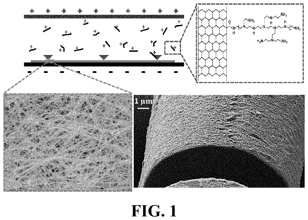
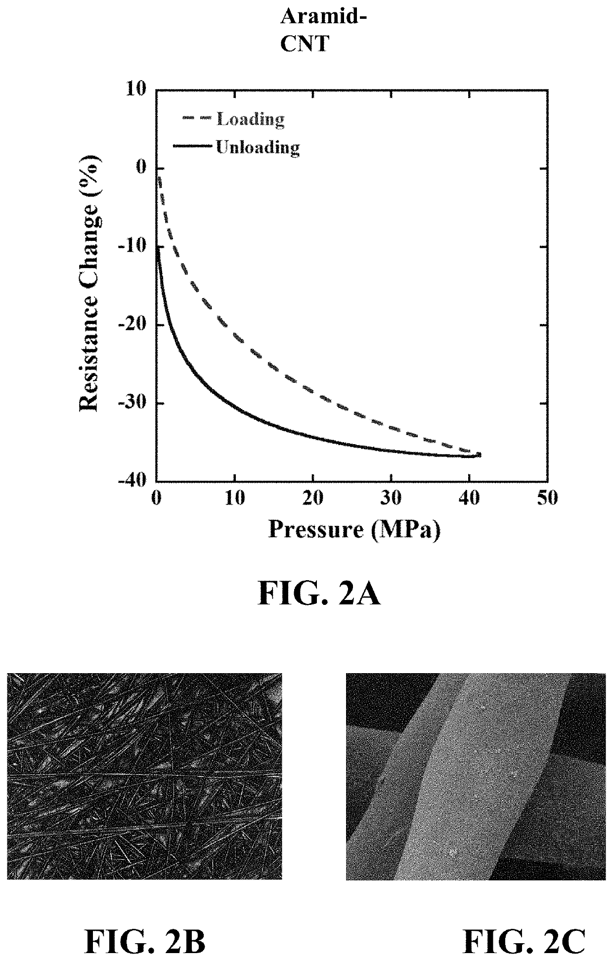
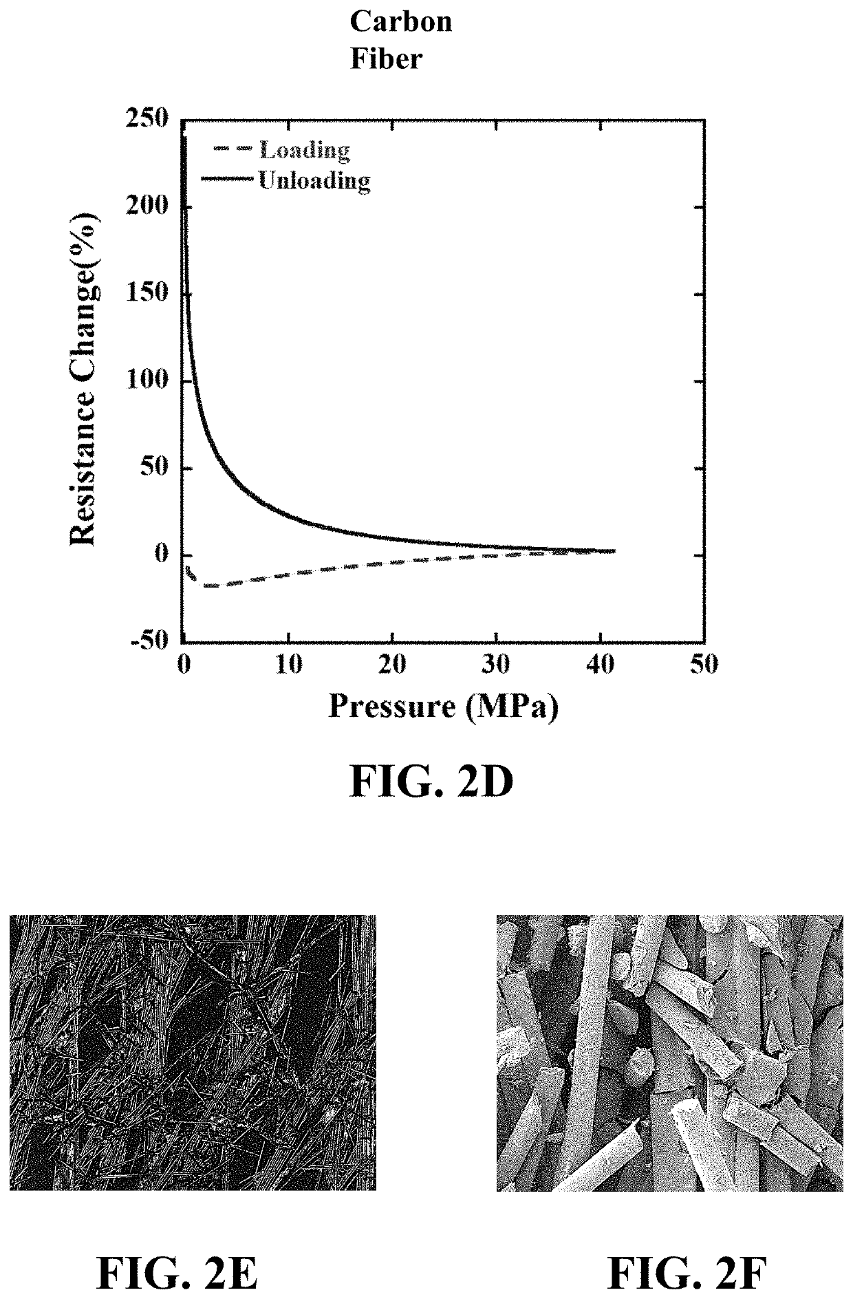
[0110]This Example demonstrates a first aspect of the invention. Specifically, it demonstrates the fabrication and testing of a piezoresistive sensor made by an electrophoretic deposition process onto nonwoven aramid fibers. The resulting sensor was integrated into footwear and used to analyze and corroborate the forces involved in walking.

[0111]This example focuses on the development and validation of novel flexible piezoresistive sensors that can be integrated into functional fabrics and footwear. Formation of thin nanocomposite films of electrically conductive carbon nanotubes (CNTs) using a scalable electrophoretic deposition (EPD) technique enables the sensing functionality. Films in the range of 250-750 nm are created on a variety of natural (cotton, wool) and synthetic (aramid, spandex) fibers using the EPD process. In this embodiment, non-woven aramid fabric with randomly oriented fibe...

example 2

nsitive Carbon Nanotube Based Sensors Using Everyday Fabrics for Human Motion Analysis

[0125]This Example demonstrates a second aspect of the present invention, namely, the fabrication and testing of highly sensitive, comfortable to wear sensors to measure a range of human joint motion. A dip-coating technique is developed to produce a thin nanocomposite coating on a commercially-available knitted fabric. The fabric sensor is then integrated into an elbow sleeve and the sensing response under elbow motion is examined.

[0126]Analyzing human motion is becoming increasingly important for patients requiring rehabilitation and athletes to improve performance. Motion capture cameras, currently used for human motion analysis are prohibitively expensive and complicated to use. There exists a critical need for developing innovative and cost-effective techniques to analyze motion outside of the laboratory. In this work, low-cost and comfortable wearable sensors can be created by coating everyda...

example 3

notube Coated Textile Sensors with Ultrahigh Sensitivity for Human Motion Detection

[0134]This Example demonstrates a third aspect of the instant invention. Specifically, we demonstrate a novel processing technique to create thin conductive films of carbon nanotubes on knitted fabrics to create flexible stretch sensors which are breathable, light-weight, and comfortable to wear. The sensing response is characterized using simultaneous mechanical and electrical characterization. Proof-of-concept is demonstrated by integrating the sensors in a knee sleeve and measuring the sensing response with knee flexion.

[0135]Highly sensitive stretch sensors are developed by coating knitted fabrics with carbon nanotubes. An innovative electrophoretic deposition approach is used to deposit a thin and conformal carbon nanotube coating on a nylon-polyester-spandex knitted fabric. The carbon nanotube coating is chemically bonded on the surface of the fibers and creates an electrically conductive networ...


PUM

PropertyMeasurementUnit
thicknessaaaaaaaaaa
thicknessaaaaaaaaaa
thicknessaaaaaaaaaa

Abstract

A piezoresistive sensor featuring a fabric of woven or nonwoven fibers coated with carbon nanotubes can be integrated with footwear or clothing to serve as a pressure sensor that can monitor and / or analyze human activity during the course of the activities of daily living of the wearer.

Description

CROSS-REFERENCE TO RELATED APPLICATION[0001]This patent document claims the benefit of commonly owned U.S. Provisional Patent Application No. 62 / 462,344, filed Apr. 16, 2019. The entire contents of this provisional patent application are expressly incorporated by reference herein.STATEMENT REGARDING FEDERALLY SPONSORED RESEARCH[0002]This invention was made with government support under Grant No. DTFH31-13-H00010 awarded by the Federal Highway Administration. Acknowledgement is further made of support from the Delaware Idea Networks of Biomedical Research Excellence (INBRE) program with a grant from the National Institute of General Medical Sciences (NIGMS) Grant No. P20 GM103446), and the state of Delaware and the National Science Foundation (NSF) Grant No. 1254540. The United States Government has certain rights in the invention.BACKGROUND OF THE INVENTION1. Field of the Invention[0003]The instant invention relates to piezoresistive sensors, and particularly those that may be integ...

Claims


Application Information

Patent Timeline
Patent Type & Authority Applications(United States)
IPC IPC(8): D06M11/74A43B3/00A43B3/12A41D1/00A43B13/14G01L1/18A61B5/11A61B5/00
CPCD06M11/74A43B3/0005A43B3/128A41D1/002D06M2101/06G01L1/18A61B5/112A61B5/6807A61B5/4528A43B13/14A41D13/1281A43B13/02A61B5/1038A61B5/1116A61B5/1123A61B5/1125A61B5/6806A61B2562/0247D06M15/61A43B3/34D06M2101/38D06M2101/12D06M2101/36A61B5/27A61B2562/0261B82Y30/00B82Y40/00G01L1/205
Inventor DOSHI, SAGARBURCH, KALEBHIGGINSON, JILLTHOSTENSON, ERIKCHAUDHARI, AMIT
Owner UNIVERSITY OF DELAWARE
Learn More