Vascular punch

a vascular and punching technology, applied in the field of vascular punching, can solve the problems of peri-operative bleeding, no large aortic punch, distorted or wrinkled connection of anastomosed tissue layer, etc., and achieve the effect of high reliability of hemostasis

Active Publication Date: 2021-01-14
3R LIFE SCI CORP
View PDF0 Cites 0 Cited by
  • Summary
  • Abstract
  • Description
  • Claims
  • Application Information

AI Technical Summary

Benefits of technology

[0009]It is an object of the claimed invention to provide a surgical instrument for making a large hole in blood vessels, wherein the cutout is clean and properly configured without fraying.
[0010]Another object of the invention is that, regarding the instrument described above, the force required to facilitate the punch action is not excessive and can be easily provided by a hand.
[0011]Still another object of the above described instrument is that the tissue cutout can be retained in the instrument after punch.

Problems solved by technology

A too large or too small incision or an irregularly enlarged hole periphery may cause mismatch of the connected graft-to-host edges during suturing, resulting in a distorted or wrinkled connection of the anastomosed tissue layer.
Poor end-to-side anastomosis may lead to peri-operative bleeding or constitute a source of post-operative thrombus formation at the uneven, wrinkled graft-to-host connection site.
It is a shame that presently there exists no large aortic punch that can help surgeons to make a big, non-frayed hole, safely and effectively, as a good foundation guaranteeing a graft connection of high quality.
It was found clinically that the adventitia of the vessel is most difficult to be separated cleanly.
The above mechanical principle and methods proposed in the prior art associated with small vascular punch cannot be extended to punching a large hole in the artery.
First, hemostasis becomes a problem when a large, 10 to 20 mm, incision is made on the artery.
Massive bleeding will be incurred due to high arterial blood pressure in the presence of a large opening, and this bleeding type is not generally allowed in a cardiovascular surgery.
Even if temporary stoppage of bleeding can be achieved, the subsequent anvil insertion will inevitably wide open the incision and cause more serious uncontrollable bleeding.
Second, the mechanism providing the shearing force for tissue separation will not be applicable for cutting a much larger hole, because the cutting area where shearing force is applied may increase substantially, requiring a much larger hand pressure to be exerted, which is often beyond the manual force a human hand can easily supply.

Method used


Image

  • Vascular punch
  • Vascular punch
  • Vascular punch

Examples


Embodiment Construction

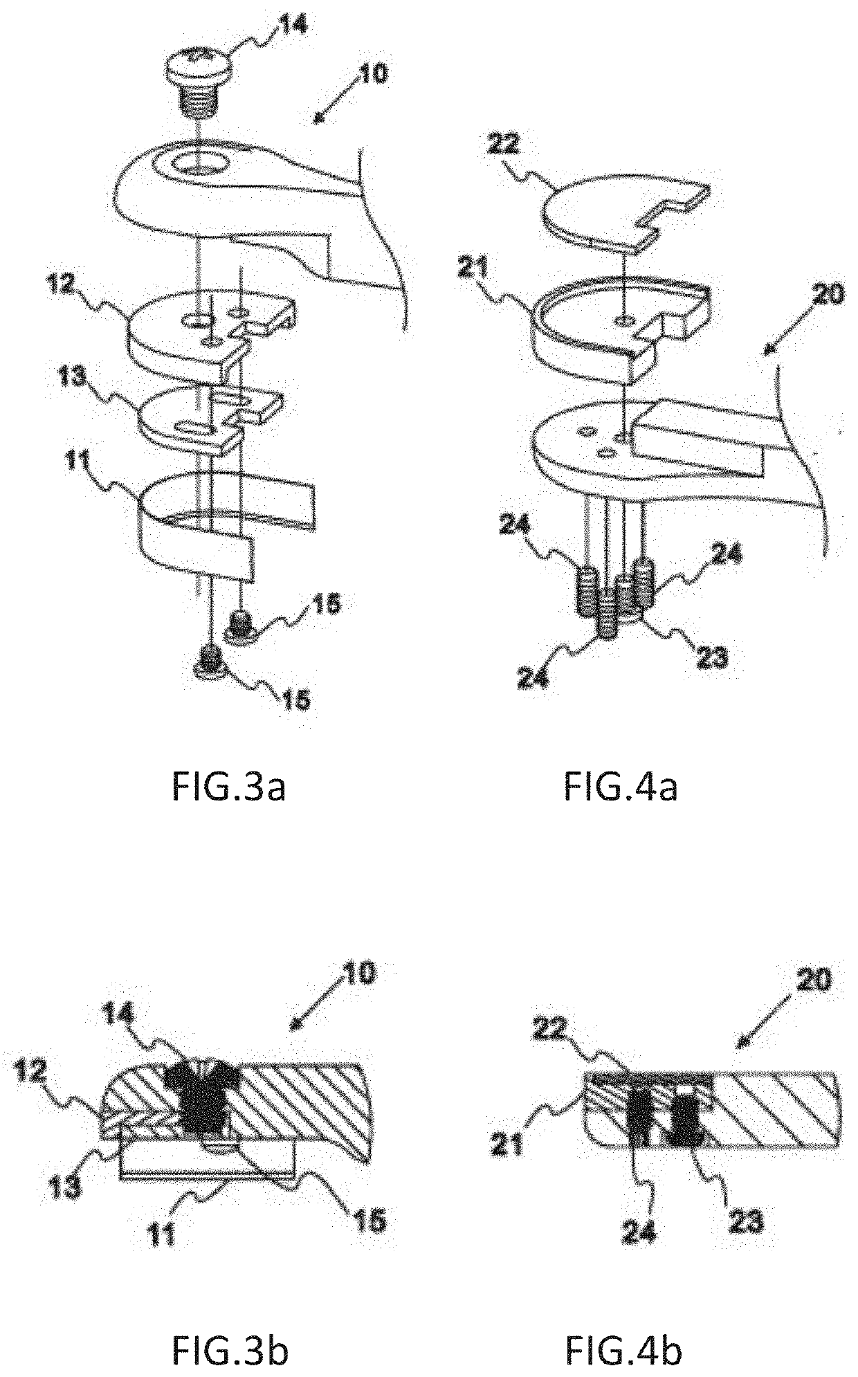
[0046]Referring to FIG. 5 and FIG. 6 the four-bar linkage type side-biting vascular punch comprises a razor-blade cutter 10, a backstop 20, a cutter lever 30, a backstop lever 40, a pair of hinge bars 50, and a handler 60. The razor-blade cutter further comprises a U-shaped razor-blade 11, a seat 12 and a locking mechanism 13. As detailed in FIG. 3a, and FIG. 3b, the seat 12 is screwed fixed with cutter 10 by a screw 14, and the razor blade 11 is squeezed against the side flange of said seat 12 using a lock plate 13. In the installation of the razor blade 11, the dull edge of the blade is first placed in contact with the corner of the side flange of seat 12, and then the blade side wall is squeezed and retained in position by the lock plate 13, followed by fixing the lock plate 13 using two lock screws 15. The cutter 10 and backstop 20 are blood-contacting, hence preferred to be made single-use to eliminate the possibility of infection. When integrated, the cutter 10 becomes an inte...


PUM


Abstract

The invention discloses a novel vascular punch employing compressive normal force for tissue separation from a targeted vessel. This invention is particularly designed for making a large round hole without massive bleeding in vascular surgery. A clean, non-frayed hole-making guided by the normal force cutting principle is realized using a site-biting punch mechanism. The side-biting vascular punch comprises a U-shaped razor blade cutter, a backstop for receiving the cutter, and a linkage mechanism, forming an aligned line of contact for normal compression force generation and thereby severing tissue out of the targeted vessel.

Description

CROSS-REFERENCE TO RELATED APPLICATIONS[0001]This application is a continuation application of a co-pending PCT international application PCT / US2018 / 057625 filed Oct. 26, 2018, the disclosure of which is hereby incorporated by reference in its entirety.BACKGROUND OF THE INVENTION1. Field of the Invention[0002]The present invention generally relates to vascular hole-making associated with cardiovascular surgery, and more specifically aims at making a large round opening, typically a hole with diameter greater than 6 mm, that cannot be satisfactorily made using the market available vascular punches.2. Description of the Prior Art[0003]Ventricular assist device (VAD) is a mechanical circulatory support modality that has advanced to a matured stage to be considered as the standard-of-the-care for treating advanced heart failure. Circulatory support is accomplished by either pulsatile or continuous-flow blood pumps, in which blood is first drawn from the heart, then pressurized or energi...

Claims


Application Information

Patent Timeline
Patent Type & Authority Applications(United States)
IPC IPC(8): A61B17/3205
CPCA61B17/32053A61B2017/00424A61B2017/00252A61B2017/1135A61B17/285A61B17/295A61B17/2804A61B2017/00778
Inventor LIN, HSIAO-CHIENLU, PONG-JEU
Owner 3R LIFE SCI CORP
Why Eureka
Try Eureka