Petroleum sludge or other wastes recycle treatment system

a technology of recycling treatment and sludge, which is applied in the field of treatment system to achieve the effects of improving the driving energy of the vehicle, ensuring air tightness, and excellent closed control

Active Publication Date: 2021-01-21
INFINIFORCE INC
View PDF3 Cites 0 Cited by
  • Summary
  • Abstract
  • Description
  • Claims
  • Application Information

AI Technical Summary

Benefits of technology

[0010]In addition, the system of the invention can be designed and installed on a vehicle, and the syngas obtained by the system can be further purified and supplied to the gas engine or fuel cell for use, so as to provide more perfect driving energy for the vehicle.
[0011]As for the raw materials in a fluid state, such as petroleum sludge, the invention breaks through the traditional idea of adopting bottom-up feeding method for petroleum sludge or other waste treatment. Because the petroleum sludge is a dense fluid, the petroleum sludge or waste can be gasified by using the principle of connecting pipe or using a pump to push petroleum sludge or fluid waste into the reactor for pyrolyzing at high temperature. That is to say, petroleum sludge or wastes in a dense fluid state are placed in the pipeline of the system, and the two ends of the pipeline are respectively arranged as the feeding end and the reactor end, between which is the structure of the connecting pipe. The reactor end extends upwards, while the raw material is input from the bottom to the top, wherein a filter can be set at the end of the reactor to reduce the mixing of ash residue into the raw material after pyrolysis reaction and to form vortex phenomenon, so as to achieve the same internal and external heating effect as described above; the feeding end can be a tank body or the pipeline is connected with the pump to the raw material tank. The bottom-up configuration of the reactor end is pipe body, cooling zone and heating zone. One side of the top of the heating zone is the slag discharge side, and the other side is the bulkhead extending upward. A closed chamber is connected to the slag discharging side as an ash residue accumulation chamber, and a buffer chamber and a bottom slag discharge chamber are arranged at the lower part of the ash residue accumulation chamber to connect the slag outlet / pipe with the outside. As mentioned above, heat dissipation fins or water cooling facilities can be installed in the ash residue accumulation chamber and the slag discharge side, etc.
[0012]Thus, the method of the invention can have the oxygen-controlled environment for pyrolyzing the petroleum sludge and other wastes of dense fluid at high temperature. Because both petroleum sludge and other wastes of dense fluids have certain air tightness, when the above-mentioned raw materials enter the pipeline from the feeding end, whether connected pipe structure or pushed by a pump, the system and the outside have formed a blocking state and the atmosphere cannot enter the system, thereby forming an excellent closed control. This bottom-up feeding method can not only create a closed oxygen-controlled environment skillfully, but also continuously feed and save a lot of action of the system. It is indeed a breakthrough in petroleum sludge and other wastes recycle treatment technology.
[0013]It must be pointed out that if the system is set up by the concept of connecting pipe, when the pyrolysis of petroleum sludge and other raw materials is carried out gradually, the matched feed rate at the feeding end should be in accordance with the pyrolysis progress of the raw material by the system, so as to maintain the pressure and mass balance between the reactor end and the feeding end. Only in this way, the raw material in the pipeline can be pushed upward gradually to the heating zone, and the continuous pyrolysis reaction treatment can be carried out to keep the system in operation. In addition, it is worth mentioning that a gas collecting pipe / outlet should be installed at the top of the reactor end to transfer the syngas obtained from the pyrolysis of the petroleum sludge and other raw materials to the subsequent treatment facilities, such as gas collecting tank and purification tank, etc.
[0014]Here, another ingenious design can provide the ash residue after pyrolysis reaction of petroleum sludge and other raw materials to be automatically moved to the other side of the ash residue accumulation chamber. That is to say, install another suction pipe beside the top of the gas collecting pipe / outlet or bifurcate out from the gas collecting pipe to direct the syngas into the interior of the reaction zone. After the pyrolysis reaction is completed gradually from the bottom to the top, the ash residue is pushed upward and blown directly into the ash residue accumulation chamber, so as to avoid the ash residue accumulation upward to form the blockage of the gas collecting pipe / outlet. The suction pipe can be equipped with an additional high temperature pump to ensure the efficiency of soot blowing. The syngas from the suction and blowing treatment can eventually return to the subsequent treatment facilities, such as gas collecting tanks and purification tanks, etc. Through the gas collecting pipe / outlet. In this way, the system does not need to set up other mechanisms to clean up the ash residue, so as to avoid redundant mechanical actions, which may increase the risk of system airtightness damage.

Problems solved by technology

Moreover, as long as human civilization exists, it is an inexhaustible renewable energy source, which is indeed a precious resource worthy to be exploited and utilized.

Method used


Image

  • Petroleum sludge or other wastes recycle treatment system
  • Petroleum sludge or other wastes recycle treatment system
  • Petroleum sludge or other wastes recycle treatment system

Examples


Embodiment Construction

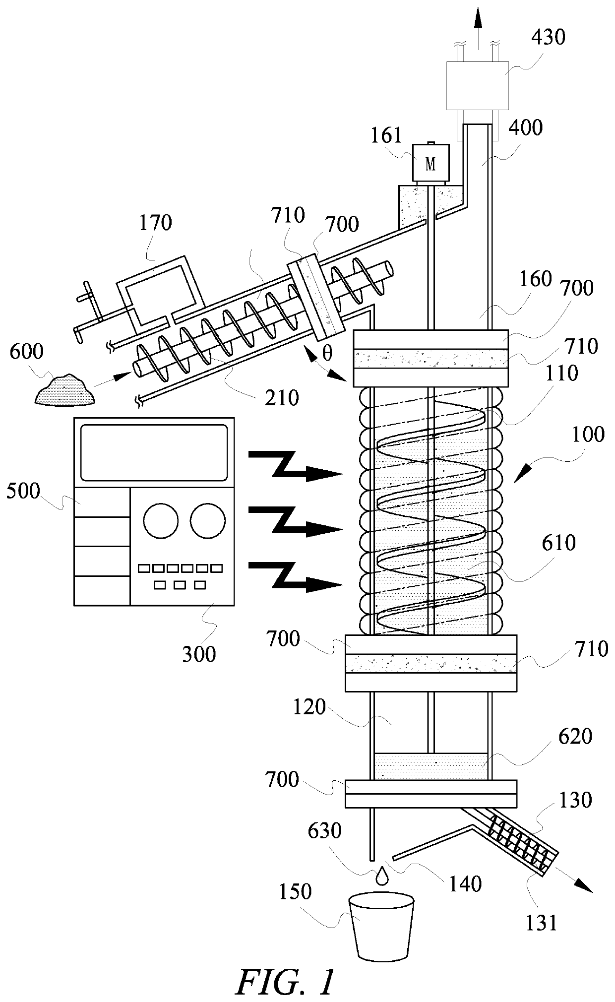
[0022]Referring to FIG. 1, this embodiment illustrates a system comprising of three main parts of feeding, gasification reactor set and slag discharging, which are combined by flange joints. After the central control unit 500 is started by power supply, the raw material of raw material pile 600 is fed into gasification reactor 100 by feeding screw conveyor rod 210 of feeding pipe 200. The gasification reactor 100 is a hollow design, covered with quartz and other insulators, and then coated with insulated cotton (not shown) to maintain the high temperature of the gasification reactor 100 as far as possible to save energy. After the raw material enters, it gradually accumulates from the bottom to the top due to gravity. Once the stacking height of the raw material reaches to fill up the heating zone 110, the central control unit 500 will issue heating instructions and start the high frequency heater 300, so that the raw material in the heating zone 110 will be heated up rapidly by con...


PUM

PropertyMeasurementUnit
electric fieldaaaaaaaaaa
temperatureaaaaaaaaaa
electric energyaaaaaaaaaa

Abstract

The invention relates to petroleum sludge or other wastes recycle treatment system, which comprises a pre-treatment operation facility for a treated matter to be treated as a raw material. A feeding unit is arranged to feed the raw material into at least one gasification reactor with a push rod or a screw for pyrolysis gasification. The upper half of the at least one gasification reactor is provided with a syngas collecting pipe which can be connected with a gas collecting pump, and the lower half is provided with a liquid petroleum output pipe and an ash residue outlet, in which the ash residue outlet can be provided with a spiral pipe to draw the ash residue out. The petroleum sludge and other wastes in a dense fluid state are transported from a raw material tank to the at least one gasification reactor end which is bent upward through at least one pipe body, and the feeding mode of pyrolysis gasification of the raw material from below to upper of the gasification reactor is adopted. The top of the at least one gasification reactor is provided with a syngas collecting pipe, and the other side is provided with an ash residue accumulation chamber. The ash residue can be centralized and discharged through the lower buffer chamber and the slag discharge chamber, so as to convert the petroleum sludge or other wastes into more energy-efficient syngas providing human beings as users of electric or thermal energy.

Description

BACKGROUND OF THE INVENTION1. Field of the Invention[0001]The invention relates to a treatment system for renewable substances such as petroleum sludge or other wastes, particularly to design high frequency electromagnetic heating technology to gasify petroleum sludge or other wastes into syngas for the purpose of using renewable energy of artificial gas to promote circular economy.2. Description of the Prior Art[0002]The cycle treatment of petroleum sludge and other wastes has always been a very troubling problem for environmental protection departments at all levels, owners and the public. At present, besides sort, recycle and reuse, garbage waste is directly buried or sent to incinerators for incineration. The petroleum sludge is being studied, tested and crushed with rice straw, wheat stem and other solids, solidified into granular form to become a RDF-5 (Refused-Derived Fuel) with calorific value, and then used as a heat source for boilers and so on.SUMMARY OF THE INVENTION[000...

Claims


Application Information

Patent Timeline
Patent Type & Authority Applications(United States)
IPC IPC(8): C01B3/24C01B3/00
CPCC01B3/24C01B3/0073C01B2203/0272C01B2203/085C01B2203/84C01B2203/1276C01B2203/16C01B2203/82C01B2203/1235Y02E60/32Y02P20/10C01B2203/066C01B2203/0266
Inventor LIAO, MING-CHEN
Owner INFINIFORCE INC
Why Eureka
Try Eureka