Air conditioning system for a vehicle and vehicle with an air conditioning system

a technology for air conditioning systems and vehicles, applied in vehicle heating/cooling devices, vehicle components, transportation and packaging, etc., can solve the problems of increasing the number of electronic components, electric driven vehicles face particular problems in heating and cooling, and the waste heat of electric engines is often not sufficient, etc., to achieve excellent thermal conductivity, good efficiency of active and passive heating and/or cooling devices, and good control

Pending Publication Date: 2021-02-25
MOTHERSON INNOVATIONS CO LTD
View PDF2 Cites 0 Cited by
  • Summary
  • Abstract
  • Description
  • Claims
  • Application Information

AI Technical Summary

Benefits of technology

[0014]It is the astonishing perception of the invention to provide a combined system of passive and active material that can be both used for heating and cooling. The usage of the control unit allows for efficient control of the vehicle's interior temperature.
[0015]By using the sensor, the temperature in the vehicle's interior can be automatically controlled without the need of additional user inputs. In a manual mode, the interior environment of the vehicle can be controlled exactly to the desires of the user. It is preferred that the control unit is readily switchable between the described automatic and man

Problems solved by technology

While in conventional, combustion engine driven vehicles the engine's waste heat is sufficient to provide all heating needs of the vehicle, electrically driven vehicles face particular problems with regard to heating and cooling.
In particular, the waste heat of electric engines is often not sufficient to provide the necessary heating for the vehicle's interior during cold days.
Moreover, the increasing number of electronic components in such vehicles, in particular displays and the like, pose an additional

Method used


Image

  • Air conditioning system for a vehicle and vehicle with an air conditioning system

Examples


Embodiment Construction

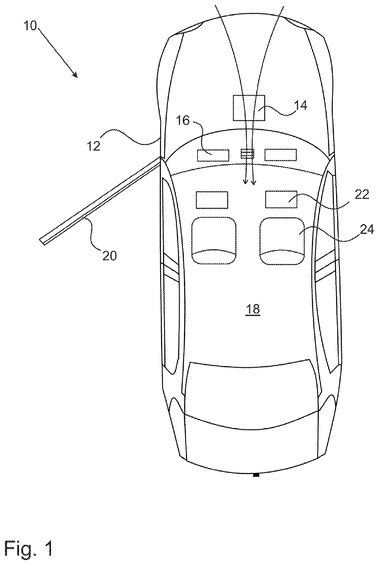
[0038]An air conditioning system 10 for a vehicle 12 comprises according to the invention at least one heat exchanger 14, which is coupled to an outside airflow.

[0039]The heat exchanger 14 comprises at least one nanomaterial, in particular a composite material containing carbon nanoparticles or inorganic nanoparticles embedded in a polymer matrix. Such nanomaterials have a particularly high thermal conductivity, thus providing a very effective heat exchanger 14. The heat exchanger 14 is thermally coupled to electronic devices 16, for example displays of the vehicle 12.

[0040]The thermal coupling between the heat exchanger 14 and the electronic devices 16 can be performed by further nanomaterial containing units, for example thermal conductors or heat pipes or the like, so that the waste heat of the electronic devices is transferred to the outside air stream in a particularly efficient manner.

[0041]It is further advantageous if the outside air stream can alternatively be directed into...


PUM


Abstract

The invention relates to an air conditioning system for a vehicle, in particular an electric vehicle, comprising at least one active heating and/or cooling device, at least one passive heating and/or cooling device, and a control unit for controlling the at least one active and the at least one passive heating and/or cooling device, wherein
    • the at least one active and the at least one passive heating and/or cooling device each comprises a nanomaterial,
    • the at least one passive heating and/or cooling device comprises a thermal conductor element, which is thermally coupling at least one electronic device, in particular a display, to an outside air stream,
    • the at least one active heating and/or cooling device comprises a nanoparticle containing resistive heating element for actively heating and/or the nanomaterial of the at least one cooling device is brought into contact with a cooling fluid in addition to an outside air stream for actively cooling, and
    • the control unit is adapted to control the at least one active and the at least one passive heating and/or cooling device depending on an input from at least one sensor, in particular a temperature sensor, and/or depending on at least one user input.
The invention further relates to a vehicle with such an air conditioning system (10).

Description

BACKGROUND1. Field of the Invention[0001]The invention relates to an air conditioning system for a vehicle, in particular an electrical vehicle, as well as to a vehicle with such an air conditioning system.2. Related Art[0002]While in conventional, combustion engine driven vehicles the engine's waste heat is sufficient to provide all heating needs of the vehicle, electrically driven vehicles face particular problems with regard to heating and cooling. In particular, the waste heat of electric engines is often not sufficient to provide the necessary heating for the vehicle's interior during cold days. Moreover, the increasing number of electronic components in such vehicles, in particular displays and the like, pose an additional waste heat problem. The waste heat has to be removed from such components to prevent overheating, but is usually not readily usable for any other purpose and thus radiated into the environment. Thus, to provide heating and cooling for an electrical vehicle, ...

Claims


Application Information

Patent Timeline
IPC IPC(8): B60H1/00B60H1/22
CPCB60H1/00392B60H2001/003B60H1/2227B60H1/00295B60H1/00271
Inventor KOSIDLO, URSZULAFLEMING, IAIN
Owner MOTHERSON INNOVATIONS CO LTD
Why Eureka
Try Eureka