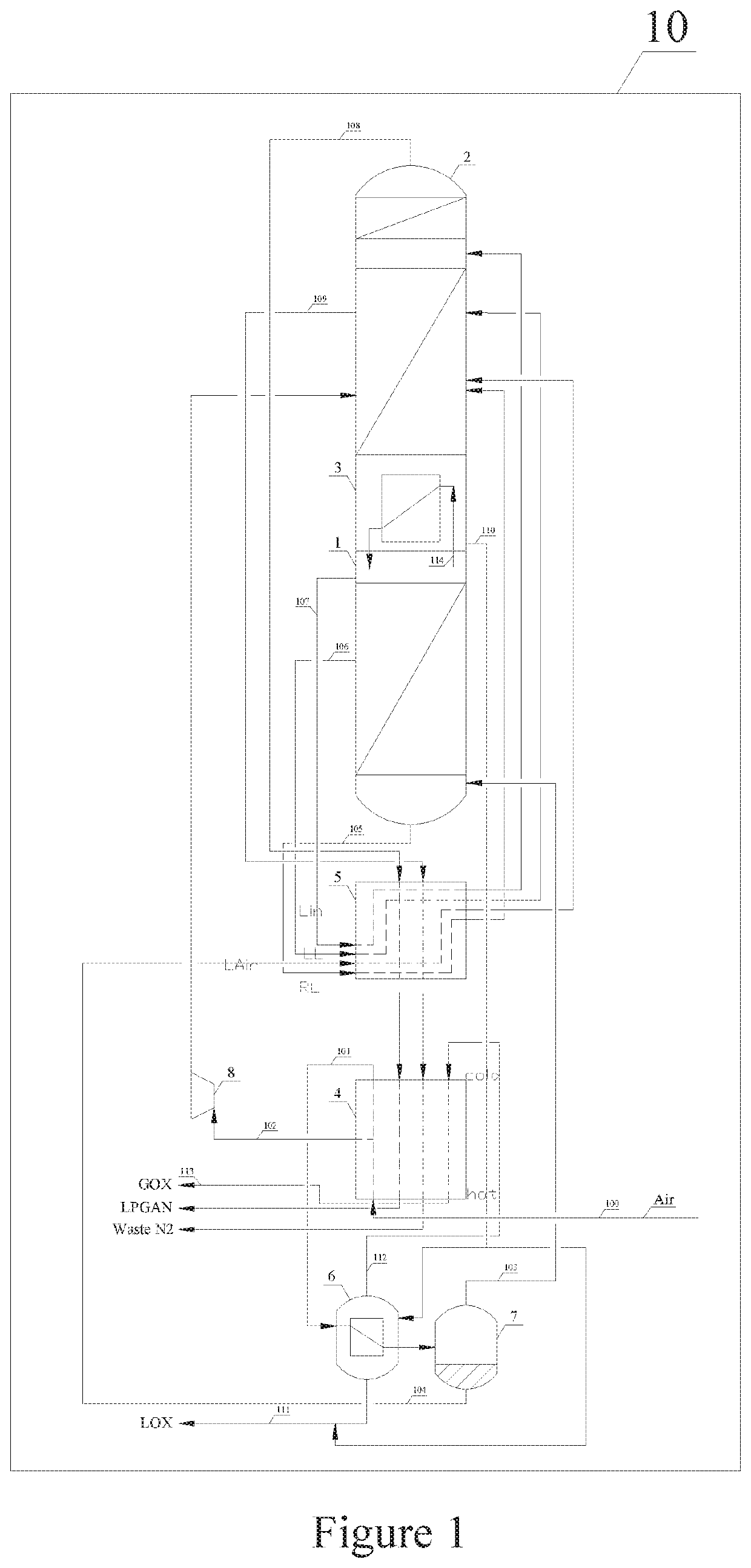
Single packaged air separation apparatus with reverse main heat exchanger

Pending Publication Date: 2021-03-04
LAIR LIQUIDE SA POUR LETUDE & LEXPLOITATION DES PROCEDES GEORGES CLAUDE
View PDF0 Cites 0 Cited by
  • Summary
  • Abstract
  • Description
  • Claims
  • Application Information

AI Technical Summary

Benefits of technology

[0006]The objective of certain embodiments of the invention is to optimize the arrangement of various components, including equipment and pi

Problems solved by technology

Although an extra oxygen pump may be eliminated, the layout of the device comp

Method used


Image

  • Single packaged air separation apparatus with reverse main heat exchanger

Examples


Embodiment Construction

[0015]Further features, advantages and possible applications of the invention are apparent from the following description of working and numerical examples and from the drawings. All described and / or depicted features on their own or in any desired combination form the subject matter of the invention, irrespective of the way in which they are combined in the claims or the way in which said claims refer back to one another.

[0016]Methods and devices for cryogenic air separation are known. Such an apparatus generally comprises a main air compressor, which can increase the pressure of ambient pressure feed air stream, an air cooling unit, such as a water cooling tower and an air purification unit employing adsorbents to remove hydrocarbons, carbon dioxide and water from the feed air stream. These components usually operate at temperatures at least above 0° C., thus do not need heat insulation from the atmosphere.

[0017]Many components of an air separation apparatus work under cryogenic c...


PUM


Abstract

A cryogenic air separation setup in a cold box, wherein gaseous oxygen under elevated pressure is produced through hydraulic force caused by the geodetic distance between where liquid oxygen is drawn from the distillation column and where liquid oxygen is vaporized to form gaseous oxygen, such as in an auxiliary evaporator. To increase the vertical distance between the above-mentioned two location, the components are arranged directly below one another in the following sequence: the lower-pressure column, the main condenser evaporator, the higher-pressure column, the subcooler, the main heat exchanger and the auxiliary evaporator). In particular, the main heat-exchanger is positioned with the cold-end on the top to optimize piping expenditure

Description

CROSS REFERENCE TO RELATED APPLICATIONS[0001]This application is a § 371 of International PCT Application PCT / CN2017 / 118260, filed Dec. 25, 2017, which is herein incorporated by reference in its entirety.FIELD OF THE INVENTION[0002]This invention relates to air separation process and apparatus, in particular cryogenic air separation process and apparatus.BACKGROUND OF THE INVENTION[0003]Rectification of air under cryogenic conditions to produce large amount of high purity oxygen, nitrogen is a well-known technology and has wide applications in industries such as steel, petrochemical, combustion and electronics. Cryogenic air separation apparatus for producing both nitrogen and oxygen generally comprises at least two distillation columns operating at different pressure, heat exchanging units and rotating machines such as turbines, compressors and pumps. To reduce capital investment and operational cost as well as increase reliability of the apparatus, it is advantageous to minimize t...

Claims


Application Information

Patent Timeline
IPC IPC(8): F25J3/04
CPCF25J3/0409F25J3/04206F25J2250/50F25J3/04412F25J2250/40F25J3/04303F25J3/04872F25J3/04103F25J3/0423F25J2205/04
Inventor BRIGLIA, ALAINKURTZ, REMYDAY, ERICXIE, HUALIFARA, BAPTISTE
Owner LAIR LIQUIDE SA POUR LETUDE & LEXPLOITATION DES PROCEDES GEORGES CLAUDE
Why Eureka
Try Eureka