Flattening apparatus, article manufacturing method, flattening method, and imprinting apparatus

Pending Publication Date: 2021-03-25
CANON KK
View PDF1 Cites 0 Cited by
  • Summary
  • Abstract
  • Description
  • Claims
  • Application Information

AI Technical Summary

Benefits of technology

The present invention allows for adjusting the temperature of a mold by sucking and holding it while supplying gas. This helps to prevent changes in the temperature of the material being flattened on a substrate, resulting in a better technique for flattening.

Problems solved by technology

However, techniques using a coating apparatus have difficulty in controlling level differences on the substrate in units of nanometers.

Method used


Image

  • Flattening apparatus, article manufacturing method, flattening method, and imprinting apparatus
  • Flattening apparatus, article manufacturing method, flattening method, and imprinting apparatus
  • Flattening apparatus, article manufacturing method, flattening method, and imprinting apparatus

Examples


first exemplary embodiment

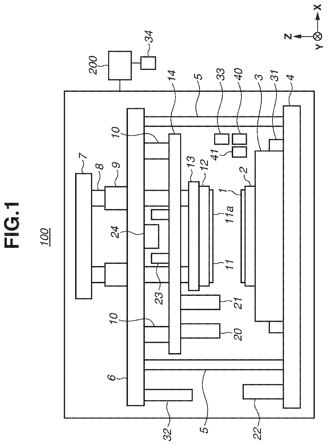
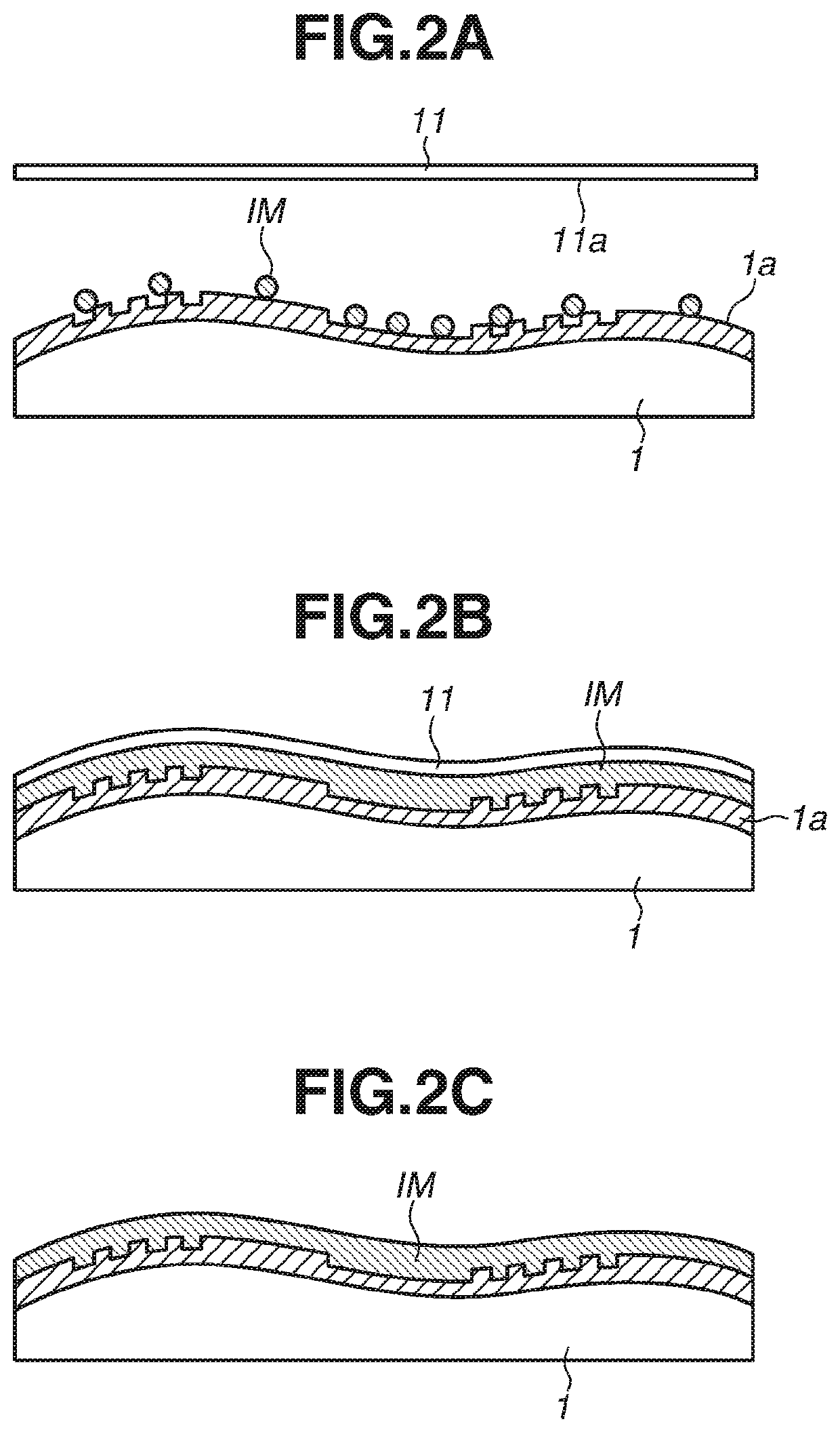
[0020]A first exemplary embodiment will be described. FIG. 1 is a schematic diagram illustrating a configuration of a flattening apparatus 100. The flattening apparatus 100 is embodied as a molding apparatus for molding a composition on a substrate 1 by using a mold 11 (template). In the present exemplary embodiment, the flattening apparatus flattens the composition on the substrate 1. The flattening apparatus 100 forms a broad or local flat surface of the composition on the substrate 1 by curing the composition in a state where the component on the substrate 1 is in contact with the mold 11, and then separating the cured composition and the mold 11.

[0021]A typical base material of the substrate 1 is a silicon wafer. However, this is not restrictive. The substrate 1 may be freely selected from among conventional semiconductor device substrates including an aluminum, titanium-tungsten alloy, aluminum-silicon alloy, aluminum-copper-silicon alloy, silicon oxide, and silicon nitride sub...

second exemplary embodiment

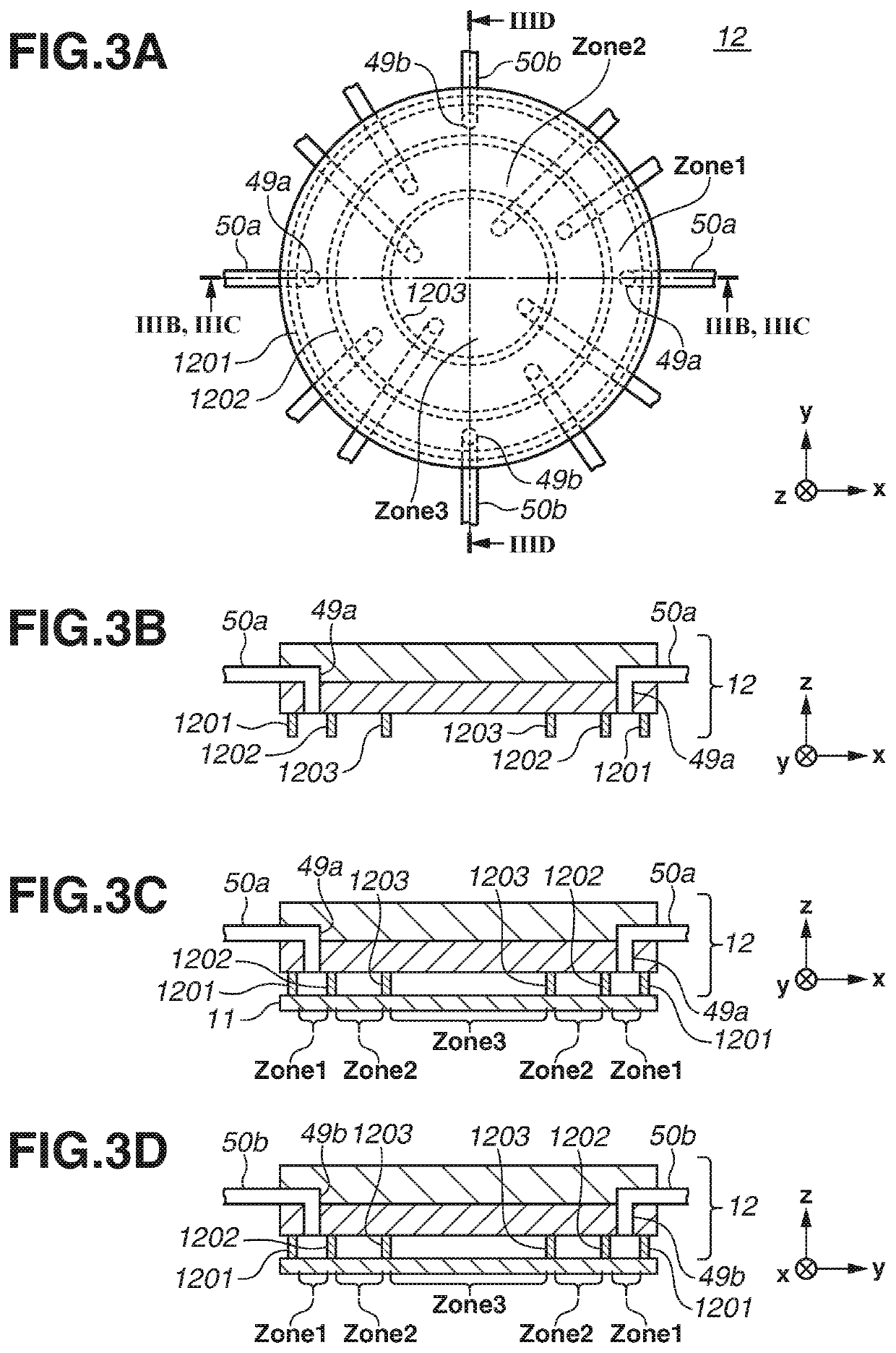
[0063]In a second exemplary embodiment, another connection example of through holes in a mold holding unit 12 with a gas supply unit and a vacuum suction pump different from the first exemplary embodiment will be described. The rest of the configuration is similar to that of the first exemplary embodiment, and a description thereof will thus be omitted.

[0064]FIG. 8 is a schematic diagram illustrating connections of the through holes in the mold chuck 12 with gas supply units 54 and vacuum suction pumps 53 according to the present exemplary embodiment. In the first exemplary embodiment, the piping 50a is connected only to the vacuum suction pump 53, and the piping 50b only to the gas supply unit 54. In the present exemplary embodiment, both the piping 50a and the piping 50b are connected to a vacuum suction pump 53 and a gas supply unit 54.

[0065]With such a configuration, the gas control unit 40 can control switching between when the piping 50a is used for gas supply and the piping 5...


PUM


Abstract

A flattening apparatus includes a mold holding unit configured to suck and hold a mold including a flat portion, a substrate holding unit holding a substrate, an exposure unit irradiating a light curing composition supplied onto the substrate with light at least via the mold to cure the composition, the composition being irradiated with the light and cured in a state where the flat portion of the mold is in contact with the composition on the substrate, a gas suction unit sucking gas from a spatial region between the mold and the mold holding unit, a gas supply unit supplying the gas to the spatial region, and a control unit controlling the gas suction unit and the gas supply unit to perform temperature adjustment processing for supplying the gas to the spatial region in a state where the mold is sucked and held onto the mold holding unit.

Description

BACKGROUNDField of the Disclosure[0001]The present disclosure relates to a flattening apparatus, an article manufacturing method, a flattening method, and an imprinting apparatus.Description of the Related Art[0002]As demand for finer semiconductor devices increases, a microfabrication technique for molding and curing an uncured composition on a substrate with a mold to form a patterned composition on the substrate has been attracting attention in addition to conventional photolithographic techniques. Such a technique is called imprinting technique and capable of forming a fine pattern on the order of several nanometers on the substrate.[0003]Examples of the imprinting technique include a light curing method. An imprinting apparatus using the light curing method forms a pattern on a substrate by molding a light curing composition supplied to a shot region on the substrate with a mold, irradiating the composition with light to cure the composition, and separating the mold from the cu...

Claims


Application Information

Patent Timeline
IPC IPC(8): H01L21/67H01L21/683
CPCH01L21/67092B81C1/0046H01L21/67115H01L21/6838G03F7/0002B82Y10/00B82Y40/00B81C1/00611B81C2201/0119
Inventor YOSHIDA, TOMOHIKO
Owner CANON KK
Why Eureka
Try Eureka