Method for manufacturing a thin-walled part

Active Publication Date: 2021-06-17
GF MACHINING SOLUTIONS AG
View PDF0 Cites 1 Cited by
  • Summary
  • Abstract
  • Description
  • Claims
  • Application Information

AI Technical Summary

Benefits of technology

[0010]It is an aspect of this invention to provide a method to manufacture a thin-walled part with an improved machining efficiency. It is in particu

Problems solved by technology

If point milling is applied, many passes are needed and consequently longer machining time is required.
Roughing is a process in which a large amount of material is removed and the surface quality is poor.
In know methods, this step is carried out by spiral point milling, which ca

Method used


Image

  • Method for manufacturing a thin-walled part
  • Method for manufacturing a thin-walled part
  • Method for manufacturing a thin-walled part

Examples


Embodiment Construction

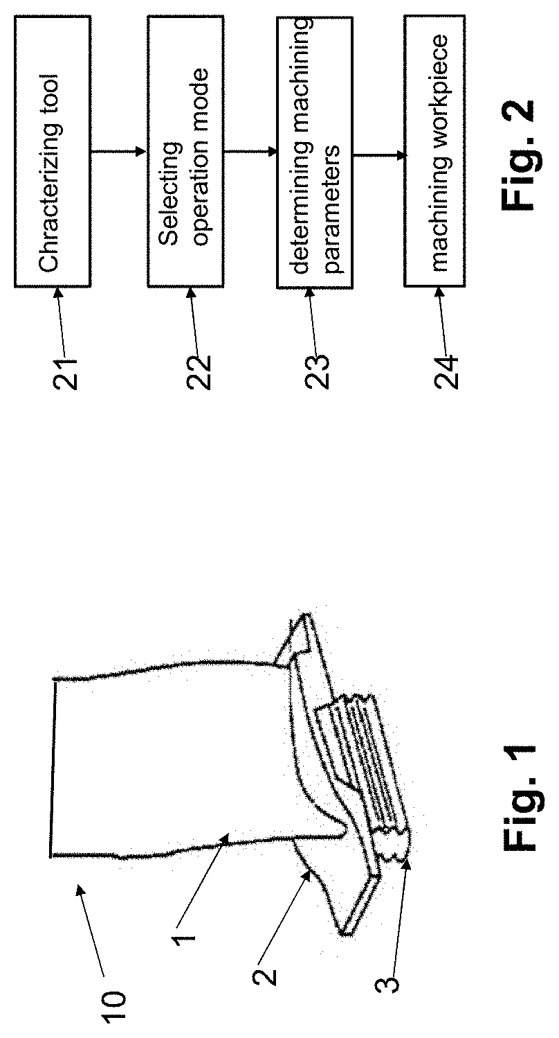
[0035]FIG. 1 illustrates a schematic of a single machined turbine blade 10 including an airfoil 1, a platform 2, and a blade root 3, which can be manufactured by the method of the present invention. However, the method of present invention is not limited to machine turbine blade and not limited to this particular shape of the turbine blade. For example, the turbine blade having additionally a shraud can also be machined by this method.

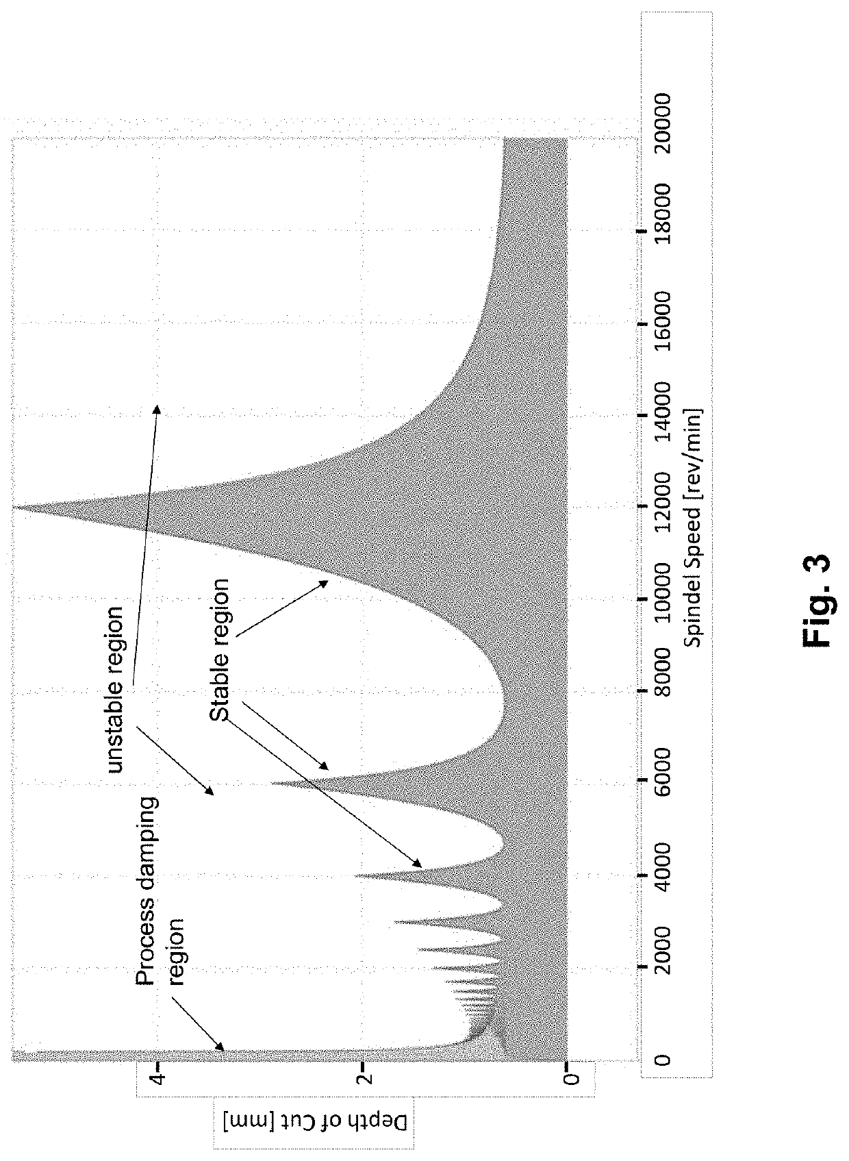
[0036]FIG. 2 shows the main steps included in the method of the present invention: characterizing a cutting tool 21, selecting an operation mode 22, determining machining parameter 23 and machining workpiece 24. Before milling the workpiece by a machine tool, at least one cutting tool used for the milling is characterized for example by a tap testing to identify the critical frequency range regarding the vibration to obtain stability lobes.

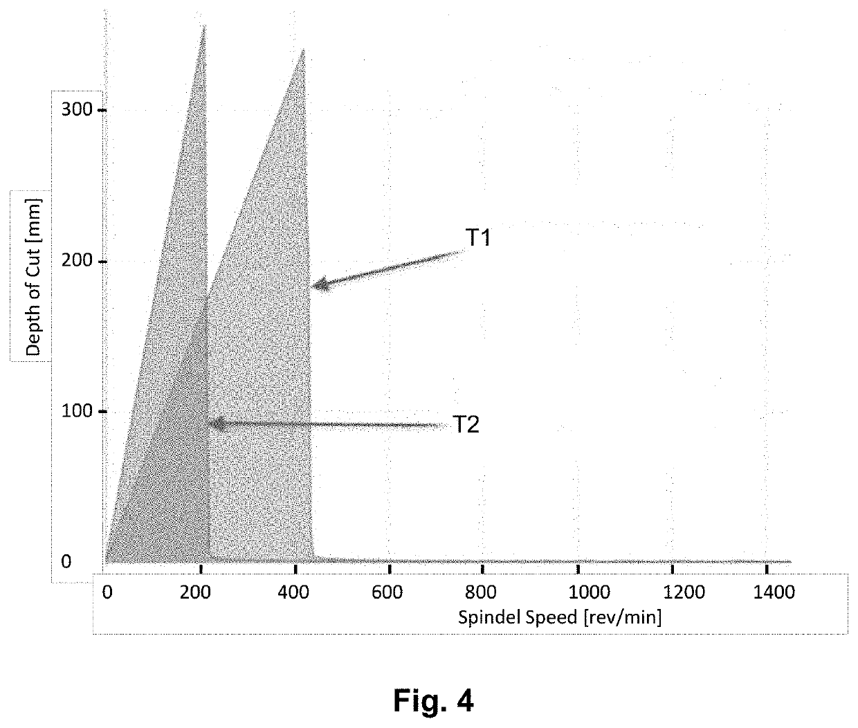
[0037]FIG. 3 shows the results of the conducted tap testing for two cutting tools T1 and T2 depicted in stability ...


PUM


Abstract

A method for manufacturing a thin-walled part having curved surfaces, in particular a turbine blade by a machine tool comprising roughing process and semi-finishing process. At least one of the roughing process and the semi-finishing process is accomplished by flank milling.

Description

CROSS-REFERENCE TO RELATED APPLICATION[0001]This application claims the benefit and priority of European Patent Application No. 19 215 452.4 filed Dec. 12, 2020. The entire disclosure of the above application is incorporated herein by reference.FIELD OF THE INVENTION[0002]The present invention is directed to a method for manufacturing a thin-walled part, in particular, a turbine blade. In further, the present invention is directed to a machine tool to manufacture the thin-walled part.BACKGROUND OF THE INVENTION[0003]The process of manufacturing parts or components having a thin-walled and curved surface can be challenging because beside the complex shape to be achieved, for many applications the machined part must fulfill high quality requirement. Therefore, a multi-axis machine tool is needed to accomplish the complex shape. Since the thin-walled workpiece has low stiffness, additional problems can be raised during the machining, such as, process-related static displacements and vi...

Claims


Application Information

Patent Timeline
IPC IPC(8): B23C3/18
CPCB23C3/18B23C2220/605B23C2215/44B23C2215/48B23C2215/52B23C2215/56B23C2220/28
Inventor FINGER, ANDREASDAY, TIM
Owner GF MACHINING SOLUTIONS AG
Why Eureka
Try Eureka