Nanopore FET Sensor with Non-Linear Potential Profile
- Summary
- Abstract
- Description
- Claims
- Application Information
AI Technical Summary
Benefits of technology
Problems solved by technology
Method used
Image
Examples
example 1
Fabrication of an Asymmetric Nanopore Field-Effect Transistor Sensor
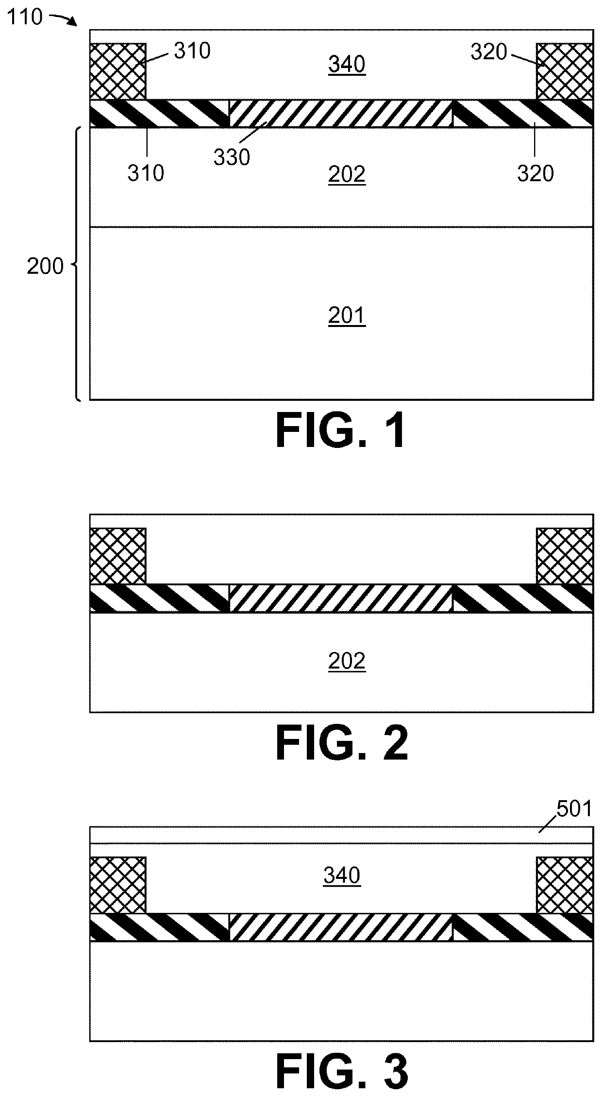
[0162]We now refer to FIG. 1. A field-effect transistor (FET) structure (110) is first provided comprising a substrate (200) comprising a buried oxide layer (202; e.g. SiO2) on a support layer (202), a channel region (330) on the buried oxide layer (202) in-between two source / drain regions (310,320), source / drain contacts (311,321) to the source / drain regions (310,320) and a dielectric layer (340) conformally covering the channel region (330), source / drain regions (310,320) and source / drain contacts (311,321). This FET structure (110) may be made based on methods which are well-known in the art.
[0163]We now refer to FIG. 2. A deep (e.g. around 50 to 100 μm deep) dry or wet etching is performed to open the bottom of the buried oxide layer (202), through the support layer (202). A freestanding FET structure is thereby obtained.
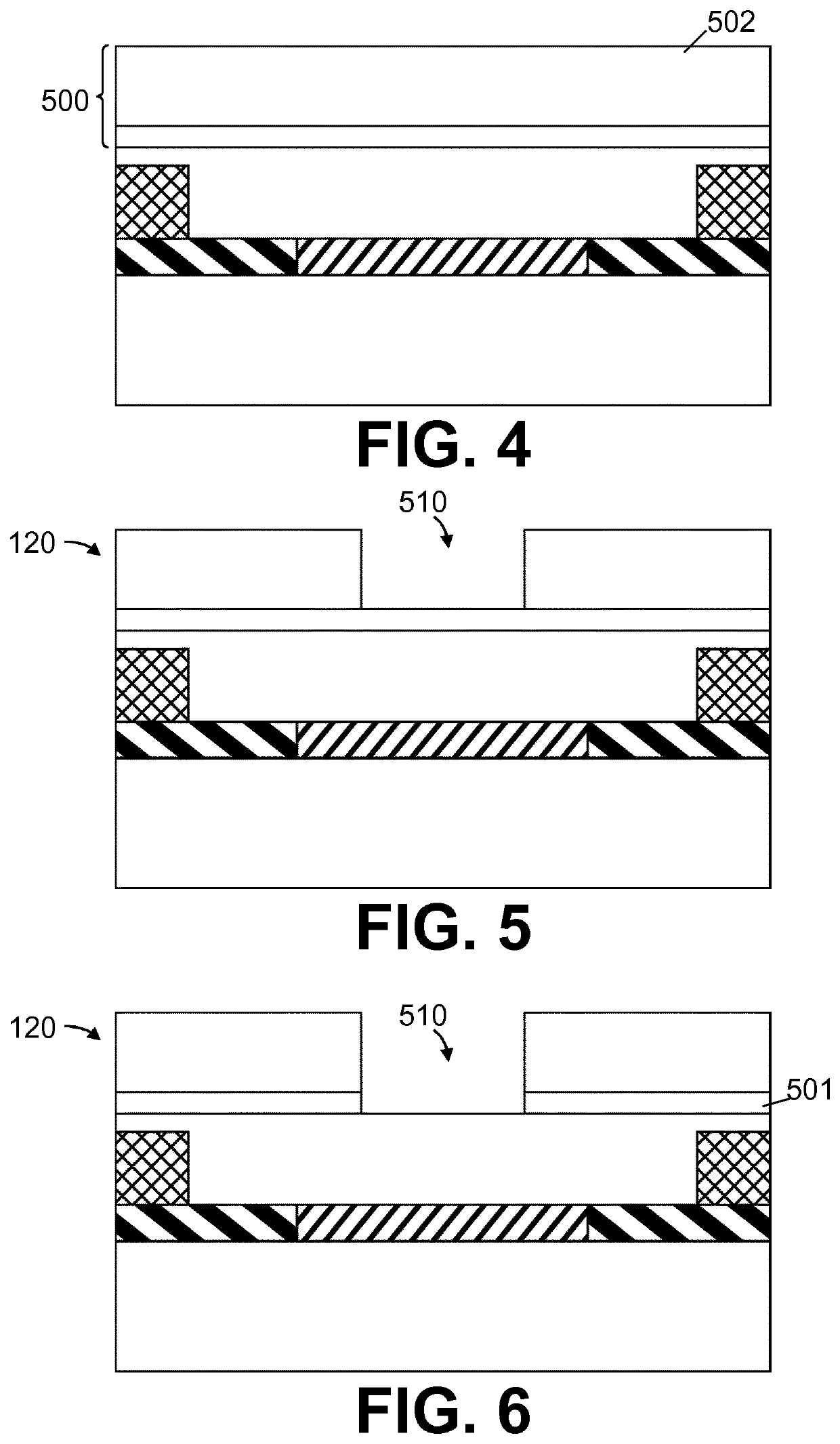
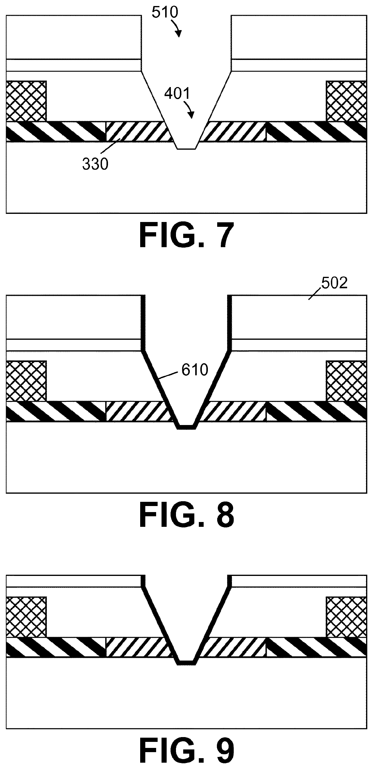
[0164]We now refer to FIG. 3. A hardmask layer (501) (e.g. Al2O3) is deposited over the diel...
example 2
Various Asymmetric Nanopore Architectures Suitable for Creating a Non-Linear Potential Profile
[0179]The architecture of a nanopore can typically be decomposed into at least the vertical profile of the nanopore and the shape of its orifices.
[0180]We now refer to FIG. 15, parts a-d, showing vertical cross-sections of various exemplary asymmetric nanopore (400) profiles in accordance with embodiments of the present invention. In FIG. 15, part a, a nanopore (400) having a width which tapers uniformly from the first orifice (410) to the second orifice (420) is shown. In FIG. 15, part b, a nanopore (400) with a step-profile is shown; e.g. the width (w) of the nanopore (400) may have one or more discrete locations at which the nanopore width changes, but said width may otherwise be relatively constant. In FIG. 15, part c, a nanopore (400) is shown having a constant width, but comprising subcomponents (431,432) of differing composition; the subcomponents (431,432) may, for example, have a d...
example 3
Effect of a Non-Linear Potential Profile
[0189]We now refer to FIG. 17, depicting characteristic potential profile curves for 20 nm long nanopores, going from their entrance (i.e. the cis orifice; Z=0 nm) to their exit (i.e. the trans orifice; Z=20 nm). The potential profile (701, 702, 703) of a symmetric nanopore (701) having a uniform width and nature across the entire depth, a step-profile asymmetric nanopore (702) and a uniformly tapering asymmetric nanopore (703) are shown, both in an empty (i.e. containing a fluid, but no analyte; full line) and filled (i.e. containing an analyte; dashed line) state. As shown in FIG. 17, the potential profile of the symmetric nanopore barely differs between the filled state and the empty state (very small ΔAV1), complicating the detection of the presence of the analyte. Conversely, for both asymmetric nanopores, the potential profile in the filled state is considerably different from that in the empty state (large ΔV2 and ΔV3); e.g. a differenc...
PUM
 Abstract
Description
Claims
Application Information
 - R&D
- Intellectual Property
- Life Sciences
- Materials
- Tech Scout
- Unparalleled Data Quality
- Higher Quality Content
- 60% Fewer Hallucinations
Browse by: Latest US Patents, China's latest patents, Technical Efficacy Thesaurus, Application Domain, Technology Topic, Popular Technical Reports.
© 2025 PatSnap. All rights reserved.Legal|Privacy policy|Modern Slavery Act Transparency Statement|Sitemap|About US| Contact US: help@patsnap.com


