
Ceramic matrix composite component including counterflow channels and method of producing

a composite component and counterflow channel technology, applied in the direction of ceramicware, machines/engines, stators, etc., can solve the problems of crack formation, crack formation, coating spallation, and extreme conditions of the cmc gas turbine components

Active Publication Date: 2021-06-24
GENERAL ELECTRIC CO
View PDF0 Cites 0 Cited by
  • Summary
  • Abstract
  • Description
  • Claims
  • Application Information

AI Technical Summary

Benefits of technology

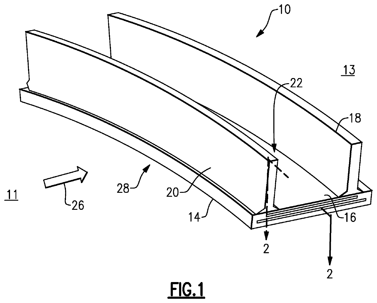
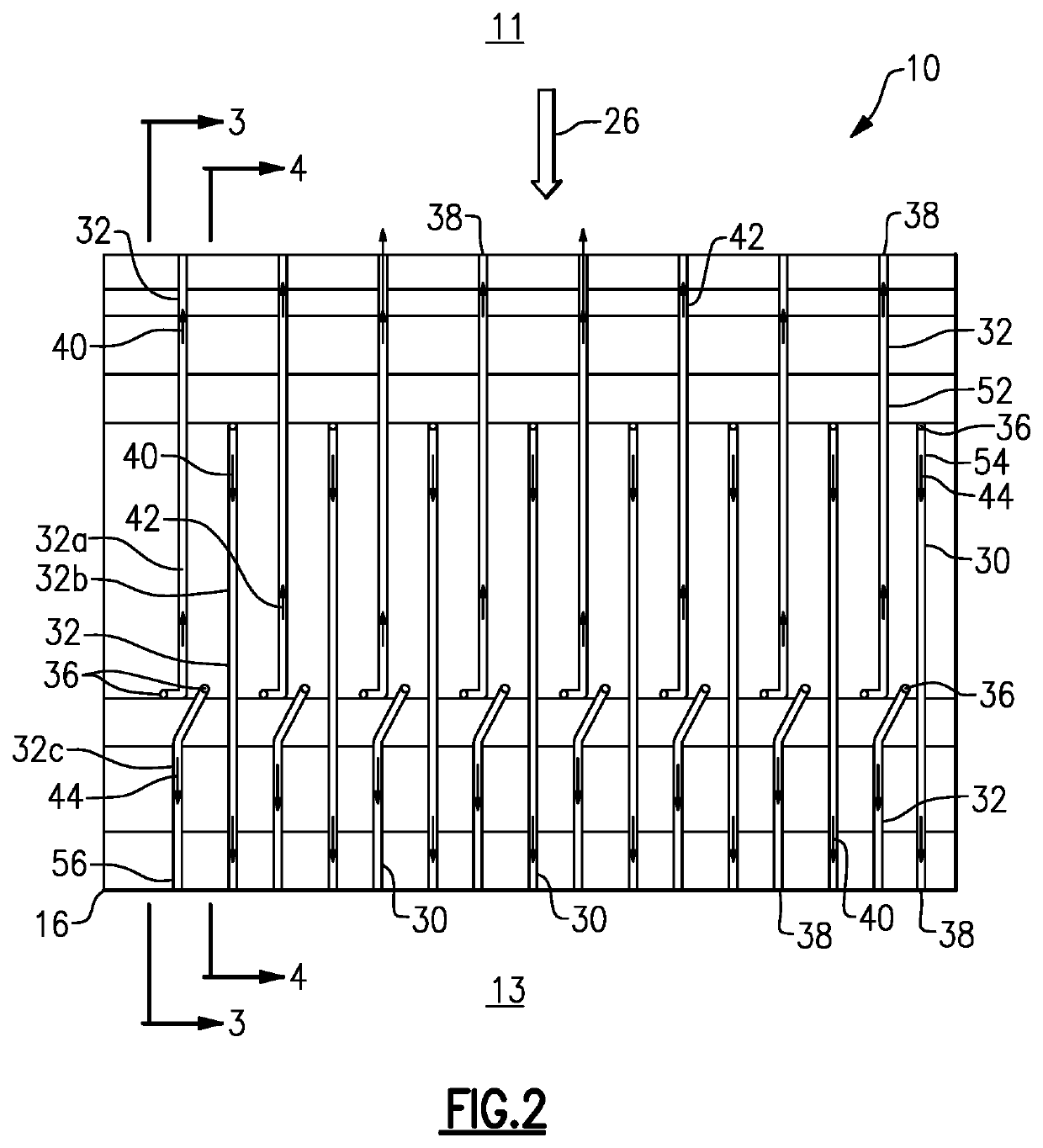
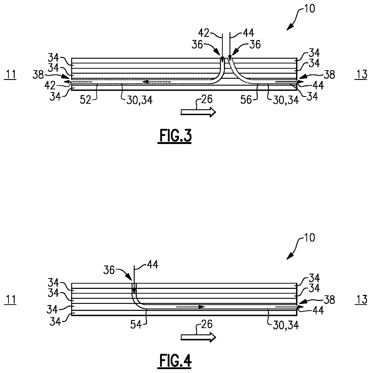
The present disclosure describes a ceramic matrix composite (CMC) component and a method of forming the component. The CMC component includes a plurality of ceramic plies and elongated functional features formed in a longitudinally extending pattern. The elongated functional features are configured in alternating flow configuration to provide a flow of fluid. The CMC component can be used in high-temperature applications where the elongated functional features are designed to protect the component from damage caused by excessive heat. The method includes forming a CMC preform and either removing sacrificial fibers or applying a fluid infiltrant to the preform to create the final CMC component.

Problems solved by technology

In many instances, the CMC gas turbine components are subject to extreme conditions in the form of extreme thermal gradients and high temperatures.
Even with the inclusion of cavities and cooling voids in the CMC component as previously described, the extreme conditions may drive crack formation, coating spallation, and recession in the CMC components.
Reduced service life from these problems prevents CMC components from realizing their full potential.

Method used


Image

  • Ceramic matrix composite component including counterflow channels and method of producing
  • Ceramic matrix composite component including counterflow channels and method of producing
  • Ceramic matrix composite component including counterflow channels and method of producing

Examples


Embodiment Construction

[0022]Embodiments of the present disclosure, for example, in comparison to concepts failing to include one or more of the features disclosed herein, enable the formation of a plurality of counterflow cooling channels in a CMC component, wherein the channels are configured in alignment with the one or more CMC layers. The inclusion of the counterflow cooling channels in alignment with the one or more CMC layers provides for maintenance of the component structural integrity. The method, according to the present disclosure, has decreased complexity with low cost, and more efficient cooling that has the ability to reduce the cooling demand and flow-rate of the part

[0023]When introducing elements of various embodiments of the present invention, the articles “a,”“an,”“the,” and “said” are intended to mean that there are one or more of the elements. The terms “comprising,”“including,” and “having” are intended to be inclusive and mean that there may be additional elements other than the li...


PUM

PropertyMeasurementUnit
Flow rateaaaaaaaaaa
Lengthaaaaaaaaaa
Pressure dropaaaaaaaaaa

Abstract

A ceramic matrix composite (CMC) component and method of fabrication including a plurality of counterflow elongated functional features. The CMC component includes a plurality of longitudinally extending ceramic matrix composite plies forming a densified body and a plurality of elongated functional features formed therein the densified body. Each of the plurality of functional features is configured longitudinally extending and in alignment with the plurality of ceramic matrix composite plies. Each of the plurality of elongated functional features includes an inlet configured in cross-ply configuration. The plurality of elongated functional features are configured to provide a flow of fluid from a fluid source to an exterior of the ceramic matrix composite component. The plurality of functional features are configured in alternating flow configuration.

Description

[0001]The present invention relates generally to gas turbines for power generation and more specifically to methods of forming ceramic matrix composite components for hot gas path turbine components for gas turbines.BACKGROUND[0002]Silicon carbide (SiC)-based ceramic matrix composite (CMC) materials have been proposed as materials for certain components of gas turbine engines, such as the turbine blades, vanes, nozzles, shrouds and buckets. Various methods are known for fabricating SiC-based components, including Silicomp, melt infiltration (MI), chemical vapor infiltration (CVI), polymer inflation pyrolysis (PIP), and oxide / oxide methods. Though these fabrication techniques significantly differ from each other, each involves the use of hand lay-up and tooling or dies to produce a near-net-shape part through a method that includes the application of heat at various method stages.[0003]As with turbine blades and vanes formed from more conventional superalloy materials, CMC blades, va...

Claims


Application Information

Patent Timeline
IPC IPC(8): F01D25/00F01D25/24F01D9/02F01D5/14C04B35/80C04B38/06
CPCF01D25/005F01D25/24F01D9/02F05D2230/10C04B35/80C04B38/0615F01D5/14F01D25/14C04B35/565C04B35/622F05D2300/2261F05D2300/6033B32B18/00C04B2237/80C04B38/065C04B2235/5212F01D11/08F05D2240/11F05D2260/204F01D11/005F05D2240/57F01D11/04F05D2260/205Y02T50/60C04B38/0003
Inventor DYSON, THOMAS EARLDECESARE, DOUGLAS GLENNSUN, CHANGJIE
Owner GENERAL ELECTRIC CO
Learn More