
Closed-cycle absorption system and method for cooling and generating power

a closed-cycle absorption and cycle technology, applied in mechanical equipment, machines/engines, steam engine plants, etc., can solve the problems of large amount of thermal energy, large thermal energy content, and large thermal energy loss of the cycle, so as to reduce the boiling point, reduce the amount of thermal energy lost, and the working fluid concentration is high.

Inactive Publication Date: 2021-07-15
GIOS BART
View PDF0 Cites 1 Cited by
  • Summary
  • Abstract
  • Description
  • Claims
  • Application Information

AI Technical Summary

Benefits of technology

The present invention relates to a method for separating a liquid absorption mixture into a working fluid and an absorption phase without heating the mixture. This method has several advantages, such as reducing thermal energy loss, increasing efficiency of heat sources, and producing a more pure gaseous phase with higher working fluid concentration.

Problems solved by technology

However, since this mixture has been heated up, for increasing the working fluid vapor pressure, it contains a lot of thermal energy.
This thermal energy is lost to the cycle.
A main drawback of distillation-based, evaporative separation techniques is that these require vast amounts of thermal energy.
As a consequence, heat is not exploited efficiently.
Yet another drawback is that distillation-based, evaporative separation techniques do not necessarily yield a high purity gaseous working fluid.
This makes the cycle even less efficient.
Another drawback resulting thereof, is that a smaller variety of heat sources is suitable; a minimum temperature, namely the boiling point of the above mixture, is required.
A problem related thereto arises during the expansion process: since the absorption fluid has a significantly lower partial vapor pressure than the working fluid, the absorption fluid will condensate first.
The formation of even moderate amounts of liquid absorption fluid, during the expansion process, has a highly negative impact on the expansion of the working fluid, and therefore on the overall efficiency of the system and the method.

Method used


Image

  • Closed-cycle absorption system and method for cooling and generating power
  • Closed-cycle absorption system and method for cooling and generating power
  • Closed-cycle absorption system and method for cooling and generating power

Examples


example 1

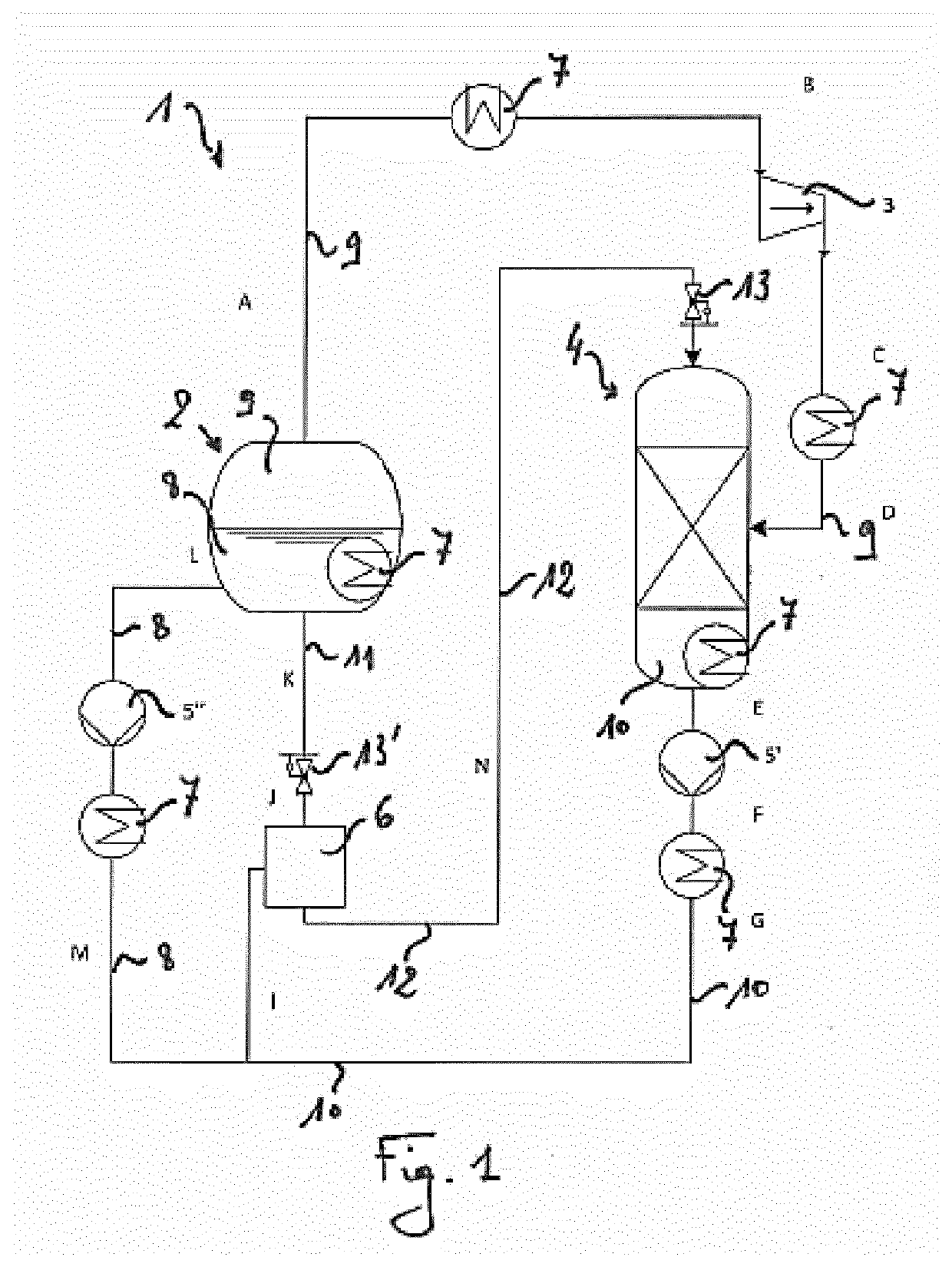
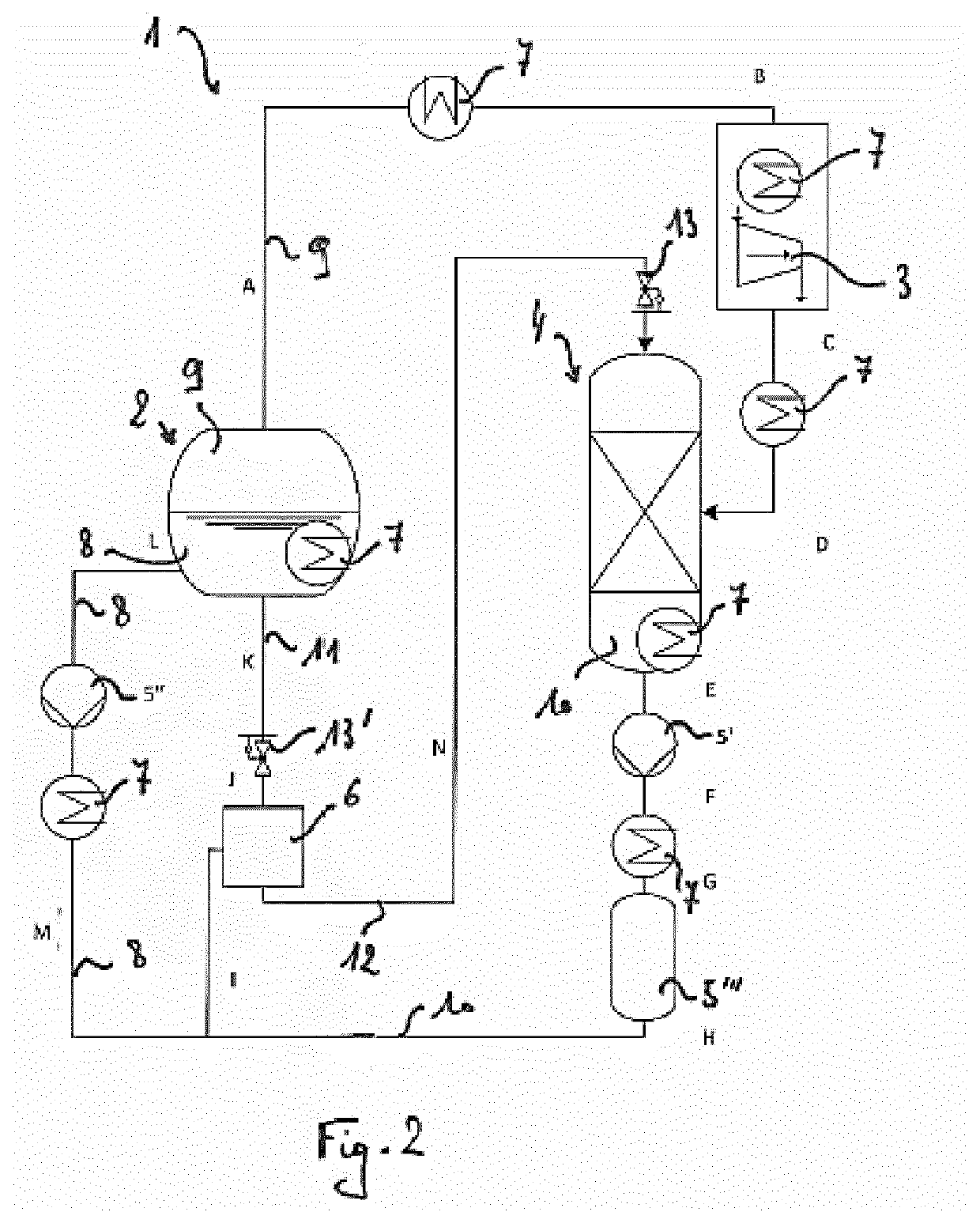
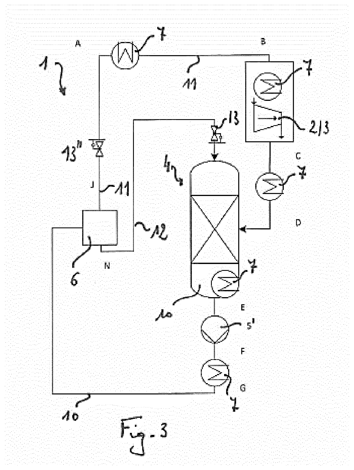
[0097]In a possible embodiment, the absorption fluid comprises water, whereby the working fluid comprises carbon dioxide. Assuming that the separator temperature is equal to about 20° C., the absorption mixture will, at pressures of about 57 bar or higher, split into a liquid absorption phase (of water saturated with carbon dioxide) and a liquid working phase (of mostly carbon dioxide). The density of the liquid carbon dioxide thereby amounts to about 775 kg / m3. The density of the water phase can be changed by adding a solute to the absorption fluid. For instance, water including sodium chlorine could be used as absorption fluid, as to make sure that the absorption phase has a substantially larger specific weight than the working phase has. By means of a gravity separation and / or centrifugal force separation process, the working phase is then mostly collected into a working effluent, while the absorption phase is mostly collected into an absorption effluent, based on their differenc...

example 2

[0098]In a possible embodiment, the absorption fluid comprises water, whereby the working fluid comprises ammonia. Assuming that the separator pressure is equal to about 1 bar, the working mixture in the separator may be cooled down to below a solidification temperature for the water—about —100° C. to 0° C., depending on the ammonia content. For working mixtures having an ammonia content of about 30% or lower, a solid and substantially pure absorption phase will thereby be formed. This absorption phase can easily be separated, for instance via filtration. The ammonia concentration in the remaining, liquid phase is thereby increased. As such, at least a preliminary or partial separation of the liquid absorption mixture is performed. However, a lot of latent heat is consumed in the solidification and melting processes, such that the efficiency of the cycle may be relatively low.

example 3

[0099]In a possible embodiment, the absorption fluid comprises water, while the working fluid comprises ammonia. The water-ammonia absorption mixture stemming from the absorber is heated and pressurized. Subsequently it is fed to a separator. The temperature in the separator amounts to about 130° C. Quite advantageously, solutions and mixtures of ammonia and water have very low viscosity values at such raised temperatures. A viscosity of less than 250 μPa·s was observed. At the same time, the pressure in the separator amounts to about 115 bar, thus at / above the condensing point of the pure working fluid (=ammonia). In the latter, the above-mentioned separator temperature was taken into account. The inventor found that, under such conditions, the homogeneous absorption mixture becomes a heterogenous mixture comprising an absorption phase and a working phase. Both are liquid phases.


PUM


Abstract

The invention discloses a method for converting thermal energy into mechanical energy, and / or for cooling, comprising the steps of at least partly evaporating a working fluid, expanding said evaporated working fluid, absorbing said expanded working fluid into a liquid absorption mixture, at least partly extracting the absorption mixture from the absorber, pressurizing said extracted absorption mixture, separating said pressurized absorption mixture into a working effluent and an absorption effluent, and feeding said working and absorption effluent to the evaporator and absorber respectively. In particular, during said separation, the absorption mixture is subjected to a pressure at or above the condensation pressure of the substantially pure working fluid, and / or to a temperature at or below the condensation temperature of the substantially pure working fluid. The invention further discloses a closed-cycle absorption system, preferably suitable for performing the method.

Description

TECHNICAL FIELD[0001]The present invention relates to methods for converting thermal energy into mechanical energy, and / or to cooling methods, which methods employ closed-cycle absorption systems. Moreover, the present invention further relates to closed-cycle absorption systems as such.BACKGROUND[0002]Closed-cycle absorption systems are known in the field of power generation and cooling.[0003]WO 2012 128 715 A1 describes a closed-cycle absorption system for converting thermal energy into mechanical energy. Thermal energy thereby originates from a low-temperature heat source, having a maximum temperature of about 150° C. Geothermal activity, solar energy, industrial waste water, and various kinds of combustion processes are regarded as suitable sources of low-temperature heat. In a first step of the cycle, an amount of gaseous CO2 working fluid is expanded through a turbine, such that mechanical energy can be extracted. Subsequently, the working gas is chemically absorbed by an abso...

Claims


Application Information

Patent Timeline
Patent Type & Authority Applications(United States)
IPC IPC(8): F01K25/06F01K25/10
CPCF01K25/065F01K25/10Y02A30/27Y02B30/62F01K11/02
Inventor GIOS, BART
Owner GIOS BART
Learn More