
Bending transducer as actuator, bending transducer as sensor, bending transducer system

a technology of bending transducer and actuator, applied in the direction of fluid speed measurement, instruments, microelectromechanical components, etc., can solve the problems of high distortion factor, high power consumption, and high demands on the linearity of the relationship between electrical signal and mechanical effect of microelectromechanical components, so as to improve the accuracy of microelectromechanical components to fulfil their intended function, improve linearity, and improve the effect of linearity

Pending Publication Date: 2021-07-29
FRAUNHOFER GESELLSCHAFT ZUR FOERDERUNG DER ANGEWANDTEN FORSCHUNG EV
View PDF0 Cites 0 Cited by
  • Summary
  • Abstract
  • Description
  • Claims
  • Application Information

AI Technical Summary

Benefits of technology

The present patent application describes a bending transducer system that can provide improved and adjustable linearity at comparable performance to existing systems. The bending transducer includes a deflectable element with two MEMS transducers that can be controlled independently to shift the phase of the output signal. The system can also have a feedback loop to dynamically compensate for asymmetrical load and improve linearity. Additionally, the patent describes a system with multiple bending transducers that can be adjusted individually to improve linearity and performance. Overall, the bending transducer system provides improved linearity and sensitivity while also allowing for individual adjustment and compensation for performance issues in different frequency bands.

Problems solved by technology

The linearity of the relationship between electrical signal and mechanical effect (transmission characteristic) of microelectromechanical components is regularly subject to high demands.
Non-linearities of the transmission characteristics adversely affect the precision with which microelectromechanical components can fulfil their intended function and have to be corrected with complex controls in the case of actuators or with complex signal processing in the case of sensors.
For example, non-linearities in the transmission characteristics of micromechanical sound transducers, i.e. loudspeakers or microphones, lead to high distortion factors and have to be corrected by the additional use of microprocessors or signal processing.
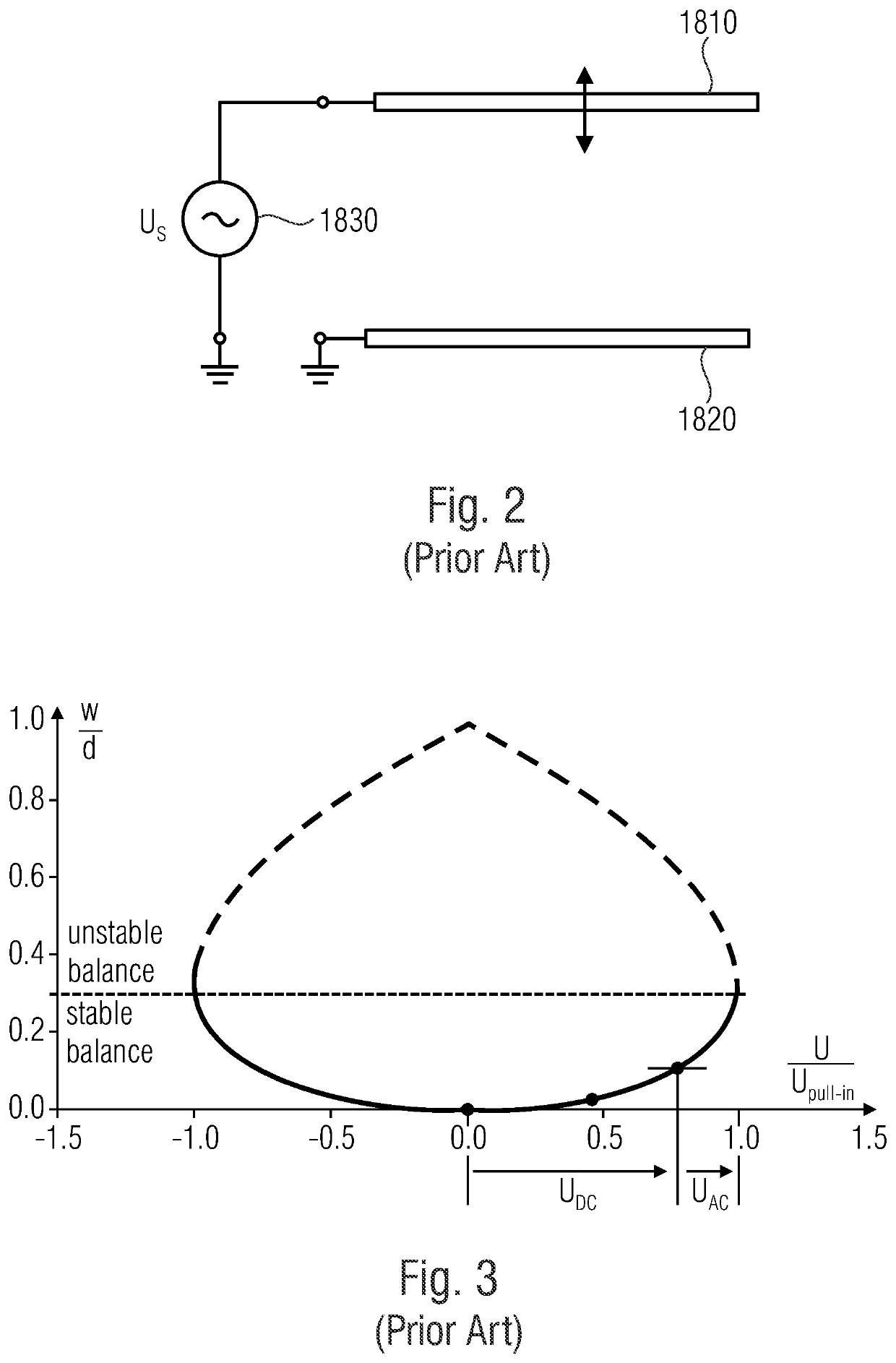
Previous design implementations of MEMS devices with improved linearity of the transmission characteristics are based on MEMS technologies with unfavorably high voltage requirements in a structurally limited dynamic range (with respect to pull-in instability) and thus a limited frequency range, which are unsuitable for mobile applications.
WO 2095185 A1 describes how to design MEMS devices having high performance with low power consumption, but does not describe possible measures to improve and adjust linearity.

Method used


Image

  • Bending transducer as actuator, bending transducer as sensor, bending transducer system
  • Bending transducer as actuator, bending transducer as sensor, bending transducer system
  • Bending transducer as actuator, bending transducer as sensor, bending transducer system

Examples


Embodiment Construction

[0054]Before the embodiments of this invention will be described below, it is first explained which considerations led the inventors to the same. In the course of these explanations, of course, references are already made to features of the embodiments described below, which should also be transferable to the same.

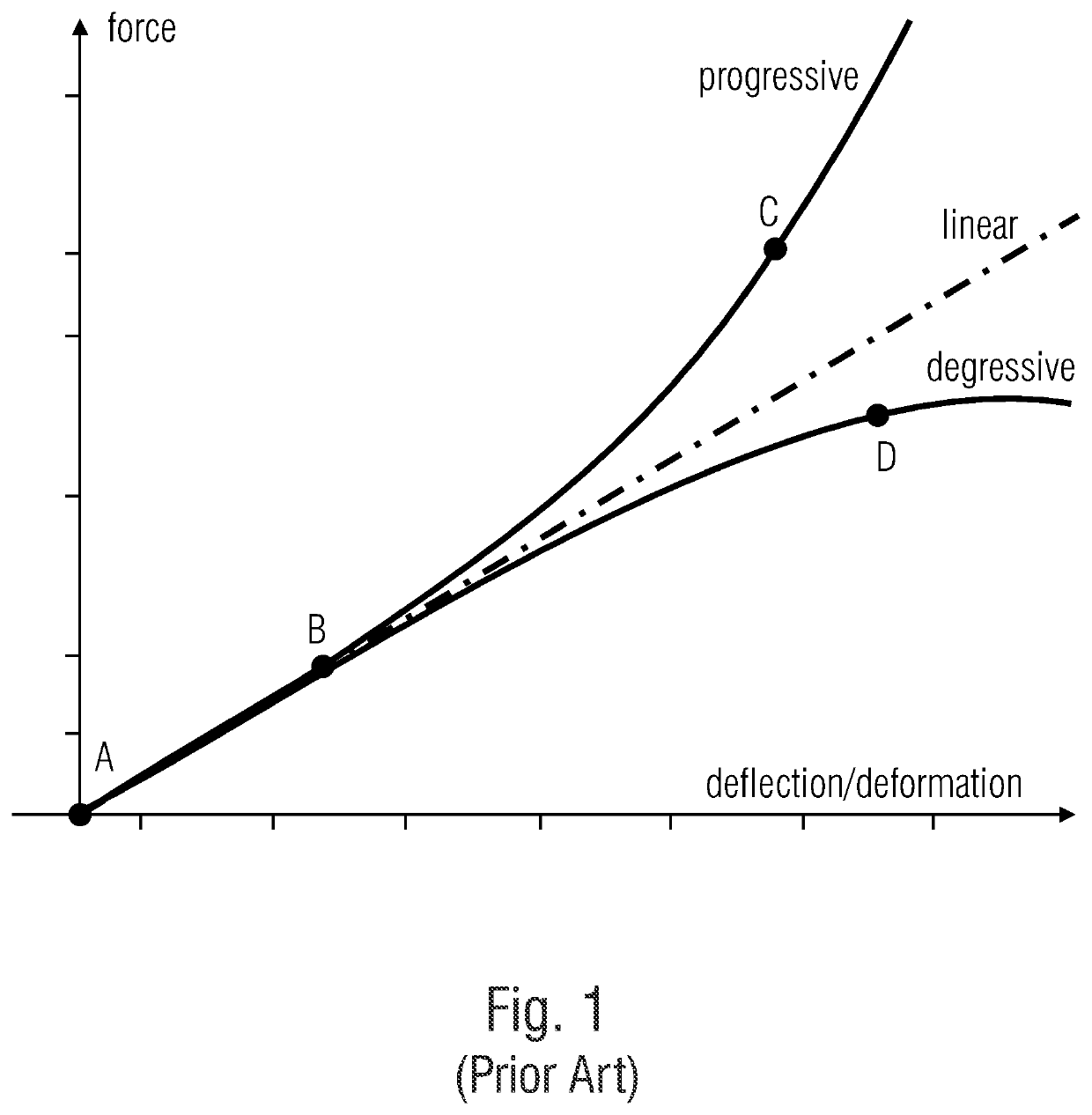
[0055]Nonlinearities of microelectromechanical components have their origin both in the electromechanical construction and its operating principle, so-called static nonlinearities, and in the dynamic behavior of the devices, so-called dynamic nonlinearities. Dynamic nonlinearities are the result of mechanical and / or electrical design features. Dynamic nonlinearities, such as intermodulation, operating point drift, subharmonic resonances, are regularly the result of static nonlinearities. The correction of existing dynamic nonlinearities is technically complex if it is practicable at all under the given circumstances.

[0056]MEMS devices of the form considered here have at le...


PUM


Abstract

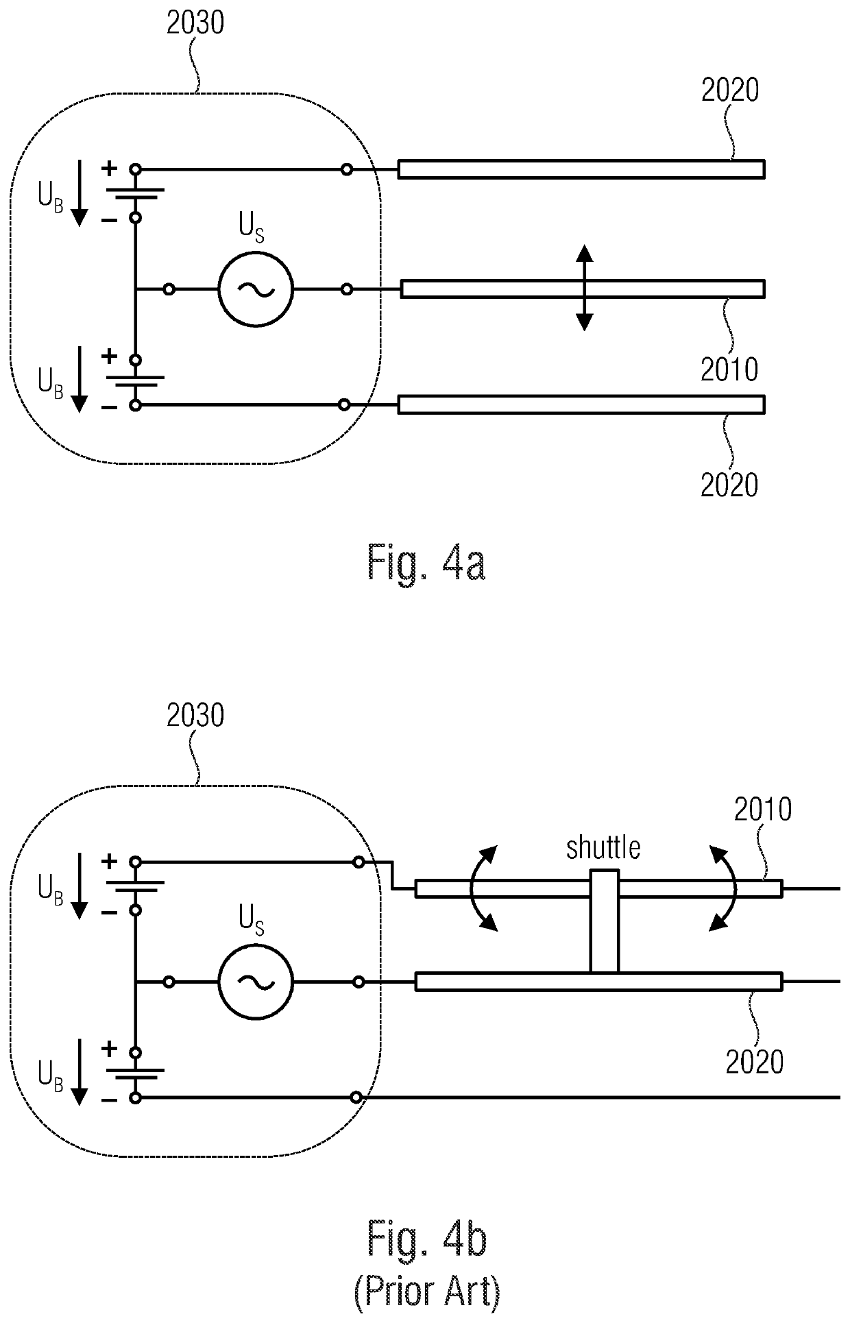
A bending transducer includes a deflectable element, a microelectromechanical transducer extending along a centroid fiber of the deflectable element deflecting the deflectable element in a first direction when a first electrical signal is applied, and a second microelectromechanical transducer extending along the centroid fiber deflecting the deflectable element in a second direction opposite to the first direction when a second electrical signal is applied, the centroid fiber being located between sides of the first and second microelectromechanical transducers facing away from each other, and an electrical control configured to vary the first and second electrical signals depending on an input signal such that a change of the first electrical signal and a change of the second electrical signal depends on the electrical input signal, and the phases of the first and second electrical signals are shifted relative to each other. A bending transducer operated as sensor is also presented.

Description

CROSS-REFERENCE TO RELATED APPLICATIONS[0001]This application is a continuation of copending International Application No. PCT / EP2018 / 078298, filed Oct. 16, 2018, which is incorporated herein by reference in its entirety.[0002]This invention relates to a bending transducer and its use as actuator or sensor and a bending transducer system.BACKGROUND OF THE INVENTION[0003]Micromechanical devices (MEMS) are needed to convert electrical signals into a mechanical effect, namely in the case of actuators, or to convert a mechanical effect into an electrical signal, namely in the case of sensors. For the purposes of this application, ‘effect’ means, for example, the carrying out work and the associated deflection or application of bending moments.[0004]The linearity of the relationship between electrical signal and mechanical effect (transmission characteristic) of microelectromechanical components is regularly subject to high demands. This applies, for example, to the use of such microelec...

Claims


Application Information

Patent Timeline
IPC IPC(8): B81B3/00B81B7/00
CPCB81B3/0021B81B3/0086B81B7/008H02N1/006B81B3/0043
Inventor SCHENK, HERMANNKAISER, BERTEHRIG, LUTZ
Owner FRAUNHOFER GESELLSCHAFT ZUR FOERDERUNG DER ANGEWANDTEN FORSCHUNG EV
Learn More