

Lambda compensation with exhaust-gas burner
- Summary
- Abstract
- Description
- Claims
- Application Information
AI Technical Summary
Benefits of technology
Problems solved by technology
Method used
Image

Examples
Embodiment Construction
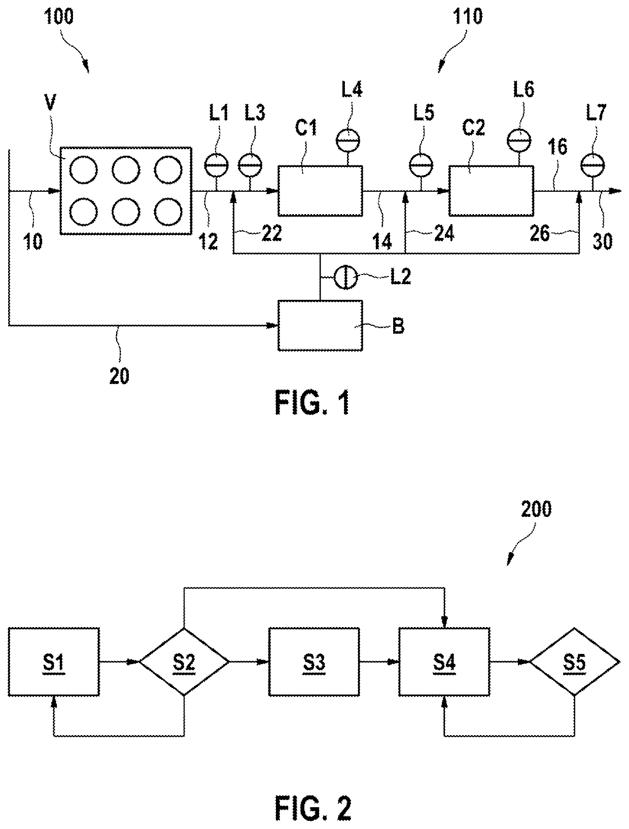
[0028]FIG. 1 schematically illustrates a vehicle 100 with an internal combustion engine V and an exhaust-gas aftertreatment system 110.
[0029]The internal combustion engine V may be designed for example in the form of an Otto-cycle engine, a diesel engine and / or a Wankel or rotary piston engine. A lean-burn engine with applied ignition may also be used as the internal combustion engine V.
[0030]The exhaust-gas aftertreatment system 110 is arranged downstream of the internal combustion engine V and comprises at least one, in the illustrated example two, catalytic converter(s) C1, C2, an exhaust-gas burner B and one or more sensors L1 to L7, of which at least one is in the form of a lambda probe L1.
[0031]The exhaust gas 22, 24, 26 of the exhaust-gas burner B can in this case be merged with the exhaust gas 12 of the internal combustion engine V at various points. Possible points for the merging are in each case upstream and downstream of the two catalytic converters, because respectively...
PUM
 Abstract
Description
Claims
Application Information