
Plasma Engine With Leptonic Energy Source

a technology of leptonic energy source and engine, which is applied in the direction of machines/engines, cosmonautic vehicles, transportation and packaging, etc., can solve the problems of electrode erosion, limited specific impulse, and low propellant usag

Active Publication Date: 2021-09-30
LOCKHEED MARTIN CORP
View PDF0 Cites 0 Cited by
  • Summary
  • Abstract
  • Description
  • Claims
  • Application Information

AI Technical Summary

Benefits of technology

The patent text describes a new type of electric propulsion system that can reach high speeds and can be used for hypersonic flight. This system uses plasma fuel, which is not limited by the energy intensity of chemical fuels. The technical effect of this patent is to provide a more efficient and powerful electric propulsion system that can overcome the limitations of current propulsion systems.

Problems solved by technology

In practice, the specific impulse is limited by the particular implementation.
High specific impulse leads to low propellant usage.
Problems include electrode erosion and general complexity of flow and current fields.
Consequently, there is no chemical-fuel based airbreathing propulsion system that can enable hypersonic flight in the range above Mach 10 or so and up to orbital speed.
Improving performance of propulsion systems is typically limited by the energy intensity of the fuel, and applies to most propulsion systems, whether rockets, jets, scramjets, bypass turbines, and the like.
Chemical fuels harvest the energy of molecular bonds and thus are limited to less than 105 J / g, leading to a performance limit of, for example, rockets at about 500 seconds ISP (specific impulse).

Method used


Image

  • Plasma Engine With Leptonic Energy Source
  • Plasma Engine With Leptonic Energy Source
  • Plasma Engine With Leptonic Energy Source

Examples


Embodiment Construction

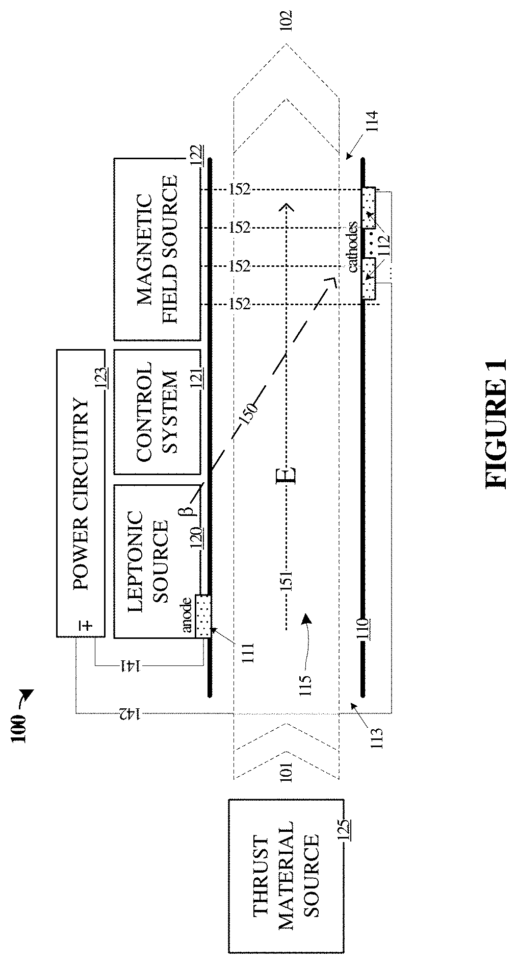
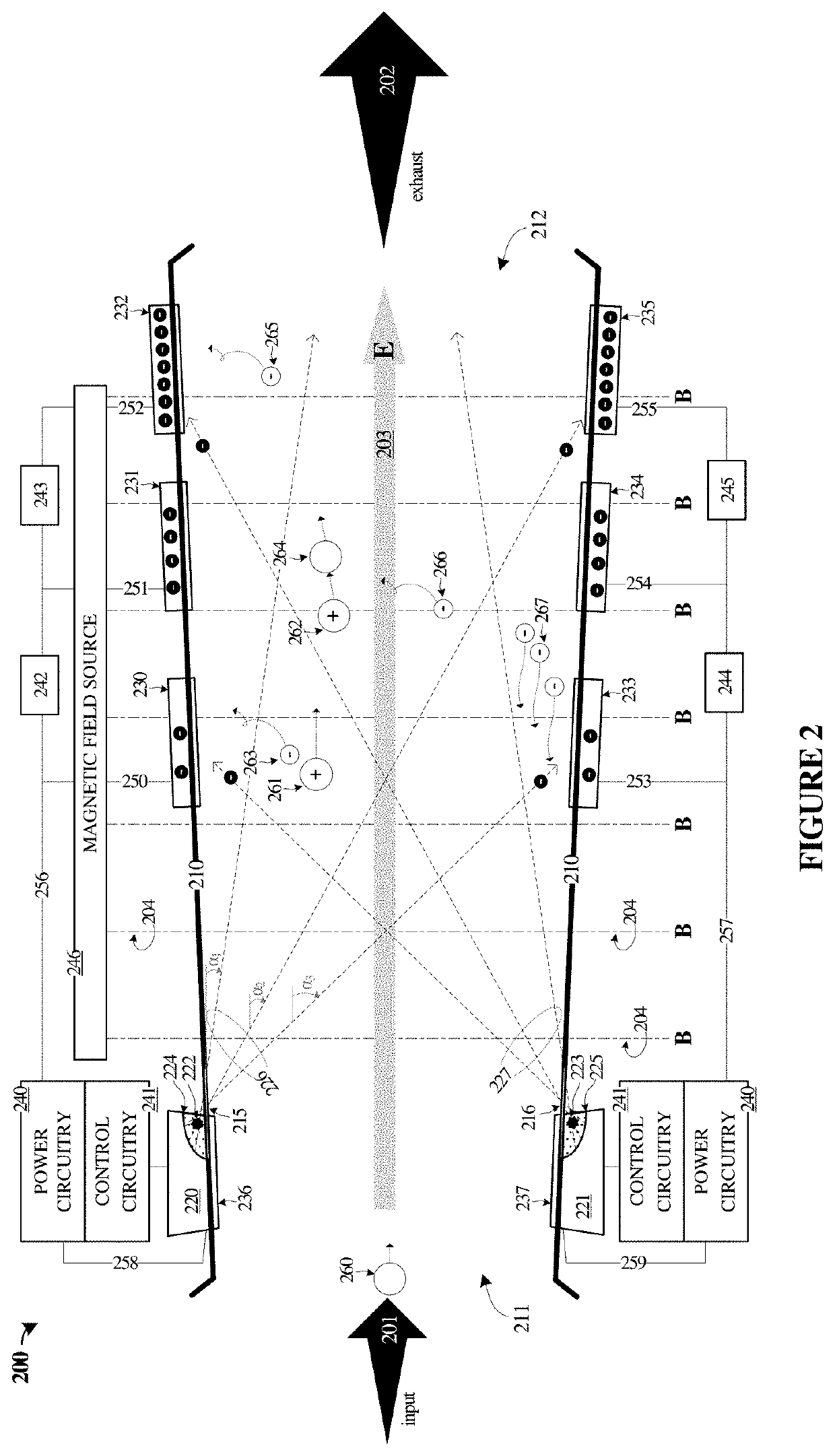
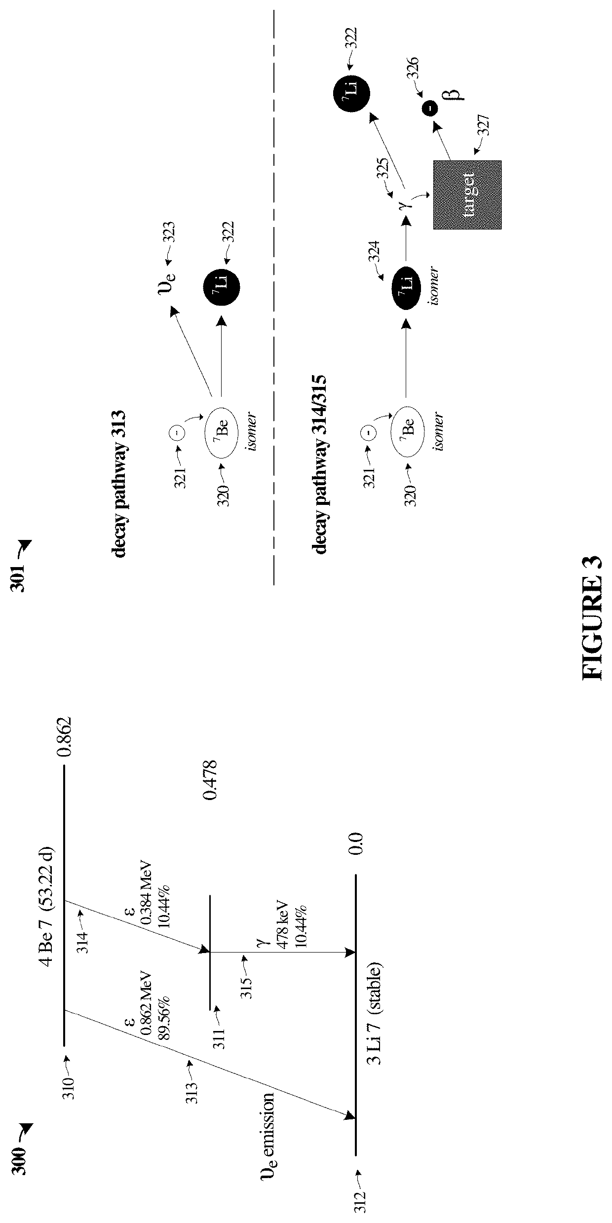
[0022]The description herein provides improvements to the performance of engine systems, propulsion systems, and associated power sources for such systems. Discussed herein are leptonic fuels, a-thermal propulsion, and direct use of leptonics. Distinct from fission or fusion, a special class of nuclear decay interactions is called beta decay. Nuclear beta decay occurs in three ways, beta−, beta+, and EC (electron capture). In these decays, a nuclear neutron (or proton) changes into a nuclear proton (or neutron) with the ejection of neutrinos and electrons (or positrons). Leptonic fuels are distinguishable from chemical fuels and from ‘hadronic’ fuels of fission, fusion, and related concepts. Leptonic fuels or “leptonics” enable specific impulse (ISP) levels of tens of thousands of seconds and higher.

[0023]In one example of leptonic fuels, nuclear isomers can be employed for energy storage. Although a naturally stable isomer state might be employed, the examples herein can employ for...


PUM


Abstract

Provided herein are various leptonic power sources, leptonic control systems, and leptonic-powered engines. In one example, an apparatus includes a housing having apertures through which material can enter and exit, and an anode coupled to the housing upstream from a cathode. A leptonic source emits beam electrons into the housing to ionize the material into a plasma according to a selectable ionization degree and deposit charge onto the cathode to establish an electric field in the plasma. A magnetic field source produces a magnetic field in the plasma at selectable angle to the flow of the plasma to at least partially entrain plasma electrons. Ions of the plasma are accelerated downstream in the housing by the electric field and impart momentum to a portion of the material to produce a thrust proportional to the selectable ionization degree of the plasma and a selectable intensity of the electric field.

Description

RELATED APPLICATIONS[0001]This application hereby claims the benefit of and priority to U.S. Provisional Patent Application No. 62 / 926,253, titled “PLASMA FUEL ENGINE,” filed Oct. 25, 2019, which is hereby incorporated by reference in its entirety.TECHNICAL BACKGROUND[0002]Propulsive engines can take various forms and be supplied using fuels that include chemical, electrical, nuclear, and other types. Engines fueled by chemical reactions, such as turbine (jet) engines or other combustion engines, require a substantial positive temperature differential between inlet air and exhaust gas. As a jet engine accelerates, especially above Mach 1, the temperature of the inlet air rises rapidly while the temperature of the exhaust gas rises more slowly, so the temperature differential diminishes. Eventually the temperature differential is extinguished, and no positive work or thrust can be produced by the engine. This happens at Mach 4 or so for a conventional turbine. One approach to higher ...

Claims


Application Information

Patent Timeline
Patent Type & Authority Applications(United States)
IPC IPC(8): F03H1/00
CPCF03H1/0081F03H1/00H05H1/54B64G1/413
Inventor ALLEN, EDWARD HENRYURIBARRI, LUKE ALEXANDER
Owner LOCKHEED MARTIN CORP
Learn More