Stack capacitor, a flash memory device and a manufacturing method thereof

a manufacturing method and stack capacitor technology, applied in the field of semiconductor devices, can solve the problems of reducing the overall chip area, increasing the manufacturing difficulty of semiconductor devices, etc., and achieve the effect of improving the capacitance per unit area, reducing the thickness of the interlayer dielectric layer, and improving the stack capacitor

Active Publication Date: 2021-09-30
SHANGHAI HUALI MICROELECTRONICS CORP
View PDF0 Cites 3 Cited by
  • Summary
  • Abstract
  • Description
  • Claims
  • Application Information

AI Technical Summary

Benefits of technology

[0021]According to the present disclosure, the existing thick silicon oxide removing step is still utilized in forming the stack capacitor area, and the silicon oxide on the uppermost layer of the interlayer dielectric layer such as silicon oxide-silicon nitride-silicon oxide (ONO) between the floating gate layer and the control gate layer is removed (using silicon nitride as a stop layer). The capacitance of the stack capacitor is improved by reducing the thickness of the interlayer dielectric layer. The capacitance per unit area is effectively improved at the same time ensuring the stability of the stack capacitor, so that the occupied area of a logic area is reduced. The manufacturing method according to the disclosure does not add any photomask, thereby there is no increase of the manufacturing cost. In addition, the manufacturing method provided by the disclosure can be compatible with the existing process flow.

Problems solved by technology

Semiconductor device manufacturing has therefore become more challenging as it moves towards the limits of physical possibilities.
This is a limiting factor in achieving reduction of the overall chip area, therefore, it is necessary to investigate how to reduce the logic area.

Method used


Image

  • Stack capacitor, a flash memory device and a manufacturing method thereof
  • Stack capacitor, a flash memory device and a manufacturing method thereof
  • Stack capacitor, a flash memory device and a manufacturing method thereof

Examples


Embodiment Construction

[0059]The disclosure is described in detail below with reference to the figures and the specific embodiments. It is noted that the embodiments described below in connection with the figures and the specific embodiments are only illustrative and should not be construed as imposing any limitation on the scope of the present disclosure.

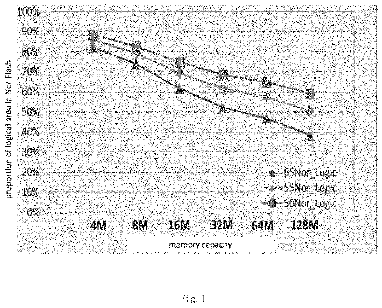
[0060]The disclosure relates to a floating gate based flash memory device structure and a manufacturing process thereof. More specifically, embodiments of the present disclosure also provide a stack capacitor structure in a flash memory device. The stack capacitor, the flash memory structure and the manufacturing method thereof can improve the capacitance of the stack capacitor, and can effectively improve the capacitance per unit area under the condition of ensuring the stability of the stack capacitor, thereby reducing the area occupied by the logic area. This technique supports continuous reduction of the unit memory size, so ensures the competitivene...


PUM

PropertyMeasurementUnit
sizeaaaaaaaaaa
sizeaaaaaaaaaa
applied voltageaaaaaaaaaa

Abstract

The present disclosure provides a stack capacitor, a flash memory device, and a manufacturing method thereof. The stack capacitor of the flash memory device has a a memory transistor structure which at least comprises a substrate, and a tunneling oxide layer, a floating gate layer, an interlayer dielectric layer and a control gate layer which are sequentially stacked on the substrate, the interlayer dielectric layer of the stack capacitor comprises a first oxide layer and a nitride layer; the stack capacitor further comprises a first contact leading out of the control gate layer and a second contact leading out of the floating gate layer. The capacitance per unit area of the stack capacitor provided by the disclosure is effectively improved, and the size of the transistor device is reduced. The manufacturing method according to the disclosure does not add any additional photomask than a conventional process flow.

Description

CROSS-REFERENCES TO RELATED APPLICATIONS[0001]This application claims the priority to Chinese patent application No. CN 202010224926.4, filed on Mar. 26, 2020 at CNIPA, and entitled “A stack capacitor, a flash memory device and a manufacturing method thereof”, the disclosure of which is incorporated herein by reference in entirety.TECHNICAL FIELD[0002]The present disclosure relates to the field of semiconductors, in particular, to a floating gate flash memory device structure and a manufacturing process thereof.BACKGROUND[0003]Flash memory devices have been widely used as the best choice for non-volatile memory applications due to its advantages of high density, low price, and electrical programmability / erasability. Some capacitor structures are placed in the flash memory devices. Typically the existing capacitor structures comprise diodes, metal oxide semiconductor (MOS) capacitors, and the like. These capacitors are formed using different device components. For example, for a 1.8V...

Claims


Application Information

Patent Timeline
Patent Type & Authority Applications(United States)
IPC IPC(8): H01L27/11536H01L49/02H01L27/06H01L29/66H01L29/788H01L27/11539
CPCH01L27/11536H01L28/40H01L27/11539H01L29/66825H01L29/788H01L27/0629H10B41/10H10B41/30H01L29/94H10B41/42Y02D10/00H10B41/44H10B41/46
Inventor TIAN, ZHILI, JUANJUANSHAO, HUACHEN, HAOYU
Owner SHANGHAI HUALI MICROELECTRONICS CORP
Why Eureka
Try Eureka