

Robot vision-based automatic rivet placement system and method
a robot vision and automatic rivet technology, applied in the direction of gripping heads, program-controlled manipulators, metal-working equipment, etc., can solve the problems of no longer meeting the use requirements, no filling mode provided for the directionally arranged rivets in the drawer, and serious affecting the accuracy of drilling and riveting equipment. , to achieve the effect of low yield
- Summary
- Abstract
- Description
- Claims
- Application Information
AI Technical Summary
Benefits of technology
Problems solved by technology
Method used
Image

Examples
Embodiment Construction
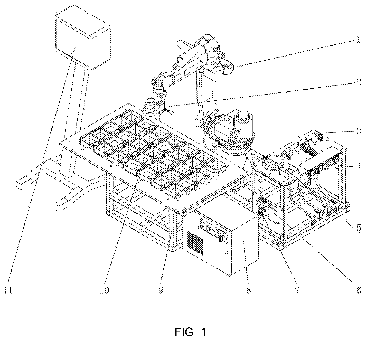
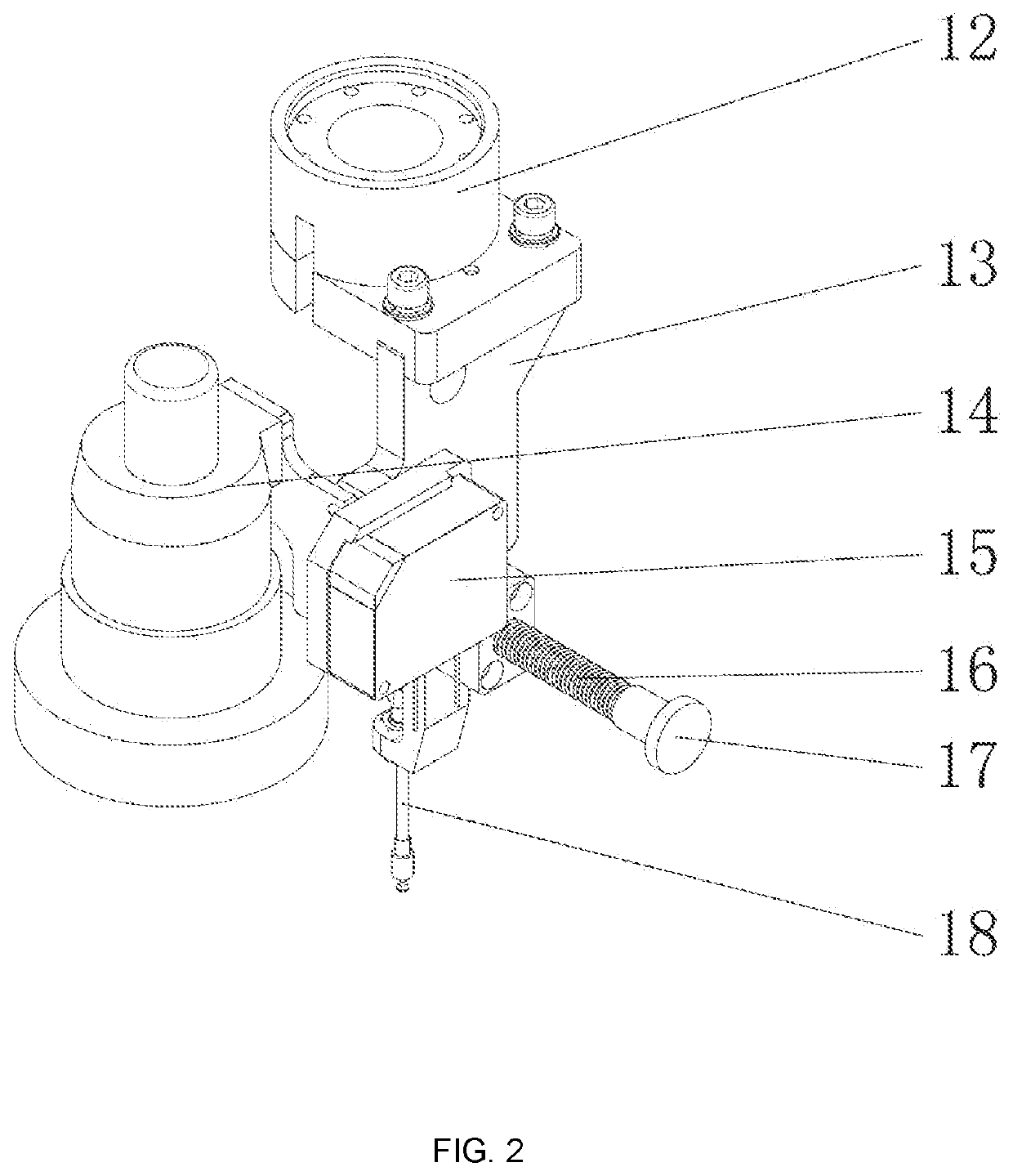
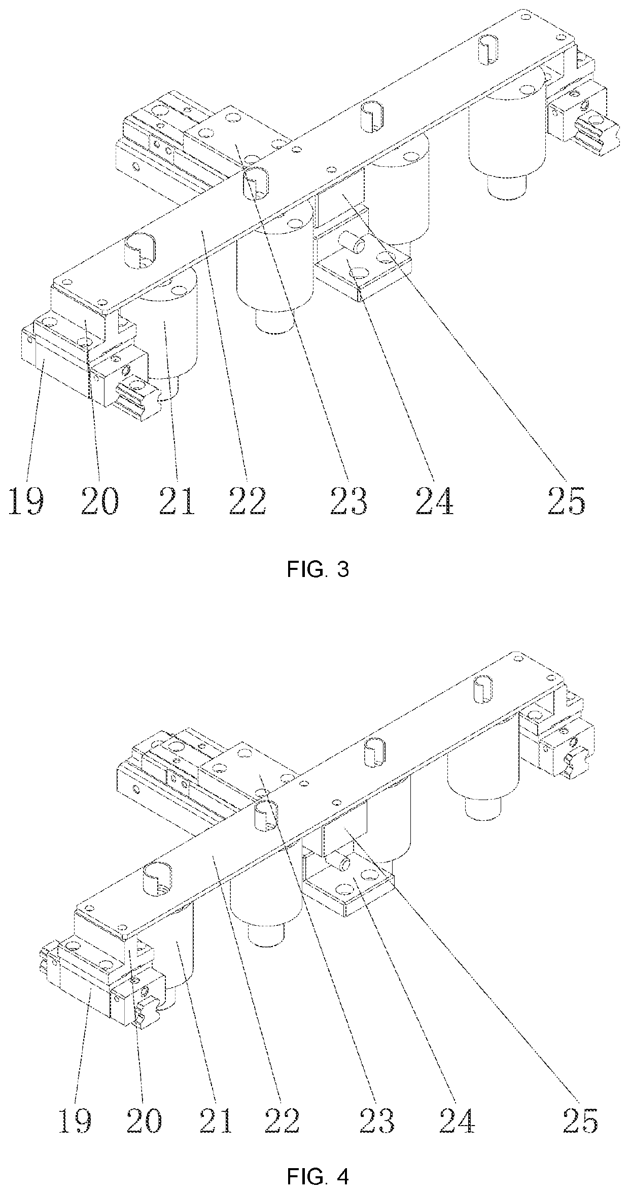
[0035]In order to make those skilled in the art better understand the technical solutions of the present invention, the present invention is further described in detail below with reference to the accompanying drawings and specific implementation manners. The implementation manners of the present invention will be described in detail below, and examples of the implementation manners are shown in the accompanying drawings, in which the same or similar reference numerals denote the same or similar elements or elements with the same or similar functions. The implementation manners described below with reference to the accompanying drawings are exemplary, and are only used to explain the present invention, and cannot be construed as limiting the present invention. Those skilled in the art can understand that, unless specifically stated, the singular forms “a”, “an”, “” and “the” used herein may also include plural forms. It should be further understood that the wording “include” used in...
PUM
| Property | Measurement | Unit |
|---|---|---|
| laser displacement sensor | aaaaa | aaaaa |
| depth | aaaaa | aaaaa |
| diameters | aaaaa | aaaaa |
Abstract
Description
Claims
Application Information