Wing integrated propulsion system

a propulsion system and integrated technology, applied in the field of aircraft, can solve the problems of reducing the benefit of such systems, reducing the design value, and increasing the induced drag

Active Publication Date: 2021-12-16
ROLLS ROYCE PLC
View PDF4 Cites 0 Cited by
  • Summary
  • Abstract
  • Description
  • Claims
  • Application Information

AI Technical Summary

Benefits of technology

[0006]Advantageously, it has been found that this positioning of the wing mounted propulsor in combination with the above lift distribution allows for reduced drag and increased propeller efficiency. Without wishing to be constrained by theory, this is thought to be a result of wing vortices generated at a span position corresponding to a maximum value of the first differential of the lift with respect to span resulting in a reduced advance ratio of the propulsor, leading to a higher propeller efficiency. Further features and advantages are provided by the disclosed arrangement, as set out below.
[0010]The wing mounted propulsor may be located aft of a trailing edge of the wing or may be located forward of a leading edge of the wing. Where the wing mounted propulsor is located aft of the trailing edge of the wing, the downwash generated upstream of the wing is reduced, thereby reducing drag. Similarly, where the propulsor is provided upstream of the leading edge of the wing, the upwash generated forward of the leading edge is reduced. In either case, drag is reduced.
[0012]The wing mounted propulsors are relatively inboard compared to previous aircraft. This reduces the yaw generated by the propulsors in the event of a propulsor failure. This in turn allows for an increase in the span of the wing, since the wing span is no longer limited by the placement of the wing mounted open rotor propulsors, which would have been provided at the wing tips in previous designs. This higher span wing further reduces lift induced drag, in view of the lower span loading implied by a larger span, and so reduces fuel use and increases range.
[0013]The propulsion system may comprise one or more further propulsors. The one or more further propulsors may be located inboard of the wing mounted propulsors and / or intermediate region of the wing. By providing further propulsors, the propulsive requirements of the aircraft can be met by dedicated propulsors, while the wing mounted propulsors can be sized and optimised to the requirements of drag reduction, rather than thrust production. Furthermore, by placing the further propulsors inboard of the intermediate region of the wing, the weight of the propulsors provides wing bending moment relief, which counteracts the wing bending moment produced by the positive lift generated by the inboard region.
[0014]The wing may comprise a folding mechanism. The folding mechanism may define a pivot point at or outboard of the position of the wing mounted propulsor and / or the neutral point of the wing. Advantageously, a large aspect ratio wing can be provided, without requiring excessive clearance during ground operations. The provision of the pivot point outboard of the wing mounted propulsor reduces the weight that must be raised by the wing folding mechanism. The provision of the pivot point outboard of the neutral point ensures that the folding portion of the wing is urged toward the deployed position by aerodynamic forces in flight, thereby increasing safety.

Problems solved by technology

However, such designs are compromised by several considerations.
Such a short span wing implies a low aspect ratio, which increases induced drag, thereby removing much of the benefit of such systems.
Furthermore, the large weight of such systems far from the aircraft centreline implies a large structural weight penalty.

Method used


Image

  • Wing integrated propulsion system
  • Wing integrated propulsion system
  • Wing integrated propulsion system

Examples


Embodiment Construction

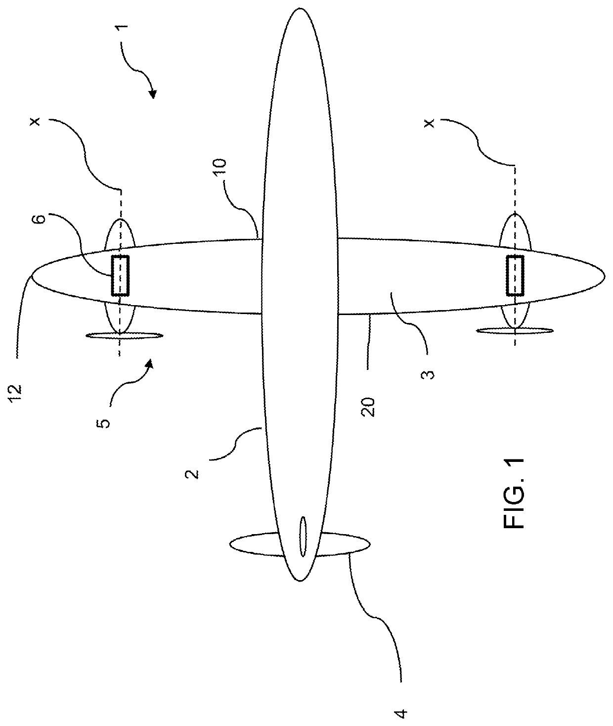
[0031]With reference to FIG. 1, a plan view of an aircraft 1 is shown. The aircraft 1 comprises a fuselage 2, wings 3, tail 4 and a propulsion system comprising a pair of open rotor wing mounted propellers 5. Each propeller 5 is mechanically driven by a respective internal combustion engine in the form of a gas turbine engine 6.

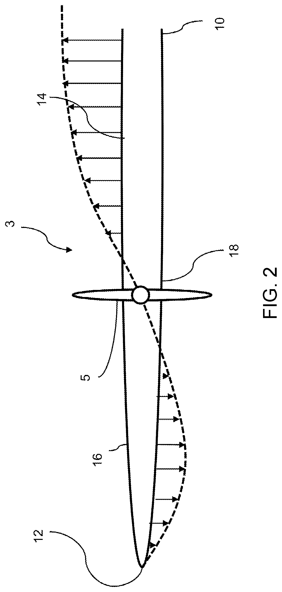
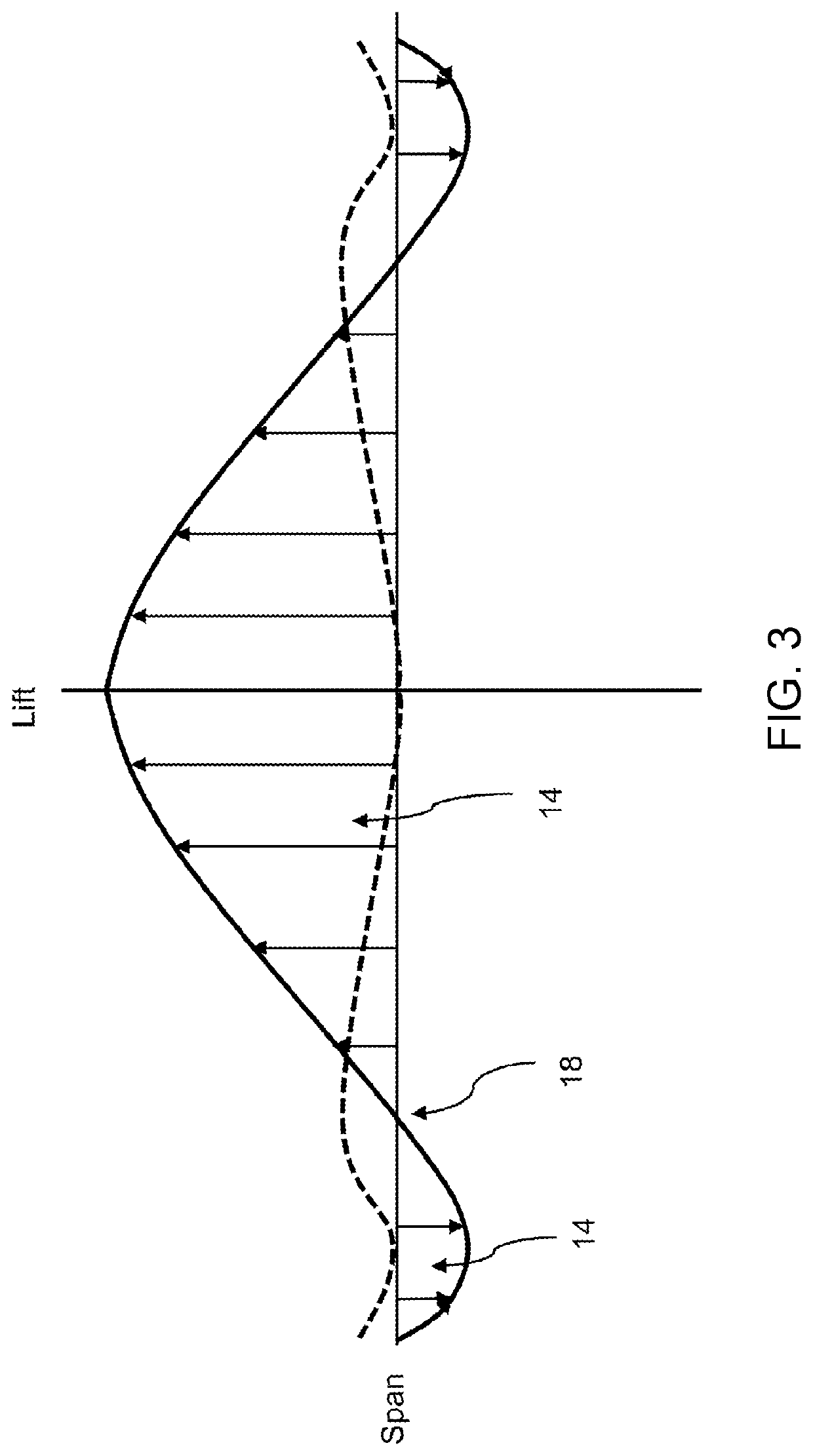
[0032]The wing 3 has a generally elliptical planform (though other planforms could be employed), and is shaped to provide a lift distribution as shown in FIG. 3. As will be understood by the skilled person, the lift distribution is the lift coefficient produced by the wing under given conditions such as angle of attack of the aerofoil, the Reynolds number of the flow, and its Mach number, as a function of the span of the wing. As is well known, the lift coefficient CL is given as:

CL=Lq⁢S

[0033]Where L is the lift force, S is the relevant surface area, and Q is the fluid dynamic pressure, in turn linked to the fluid density and flow speed.

[0034]In the present d...


PUM


Abstract

An aircraft comprising a wing having a spanwise lift distribution extending from a root to a tip, the lift distribution defining an inboard region defining a positive lift contribution, an outboard region defining a negative lift contribution, and an intermediate region defining a neutral lift contribution, the neutral region being spaced from the tip and from the root. A propulsion system is provided, comprising a wing mounted propulsor. The wing mounted propulsor has a rotational axis (x) positioned substantially at a span of the wing where a value of δLift / δSpan is at a maximum for the span of the wing, and may be located at the intermediate region along the span of the wing.

Description

CROSS-REFERENCE TO RELATED APPLICATIONS[0001]This specification is based upon and claims the benefit of priority from United Kingdom patent application number GB 2008876.1 filed on Jun. 11, 2020, the entire contents of which is incorporated herein by reference.BACKGROUNDTechnical Field[0002]The present disclosure concerns an aircraft comprising a wing integrated propulsion system, and a propulsion system for an aircraft.Description of the Related Art[0003]It is desirable to decrease aircraft drag, to reduce fuel burn and increase range. One method of reducing drag is to provide aircraft having “tip propellers”. An example experimental aircraft using such a propulsion system is the Chance-Vought XF5U. Such aircraft produce reduced induced drag (i.e. drag due to lift). Such propulsions systems also provide for increased propeller efficiency. However, such designs are compromised by several considerations. For example, by providing tip propulsors at the wing tips, a relatively large ya...

Claims


Application Information

Patent Timeline
Patent Type & Authority Applications(United States)
IPC IPC(8): B64C3/32B64C3/14B64C3/38B64D27/24
CPCB64C3/32B64C3/14B64D2027/026B64D27/24B64C3/38B64C3/00B64C11/46B64C3/56B64D27/02Y02T10/70Y02T50/40Y02T50/60B60L50/70B60L50/40B60L2200/10
Inventor MOXON, MATTHEW
Owner ROLLS ROYCE PLC
Why Eureka
Try Eureka