
Reactor and process for partial oxidation

a technology of partial oxidation and reactor, applied in the field of partial oxidation, can solve the problems of loss of carbon source, undesirable formation of soot, fouling and obstruction of conduits, etc., and achieve the effect of reducing the formation of soo

Pending Publication Date: 2022-03-31
CASALE SA
View PDF0 Cites 0 Cited by
  • Summary
  • Abstract
  • Description
  • Claims
  • Application Information

AI Technical Summary

Benefits of technology

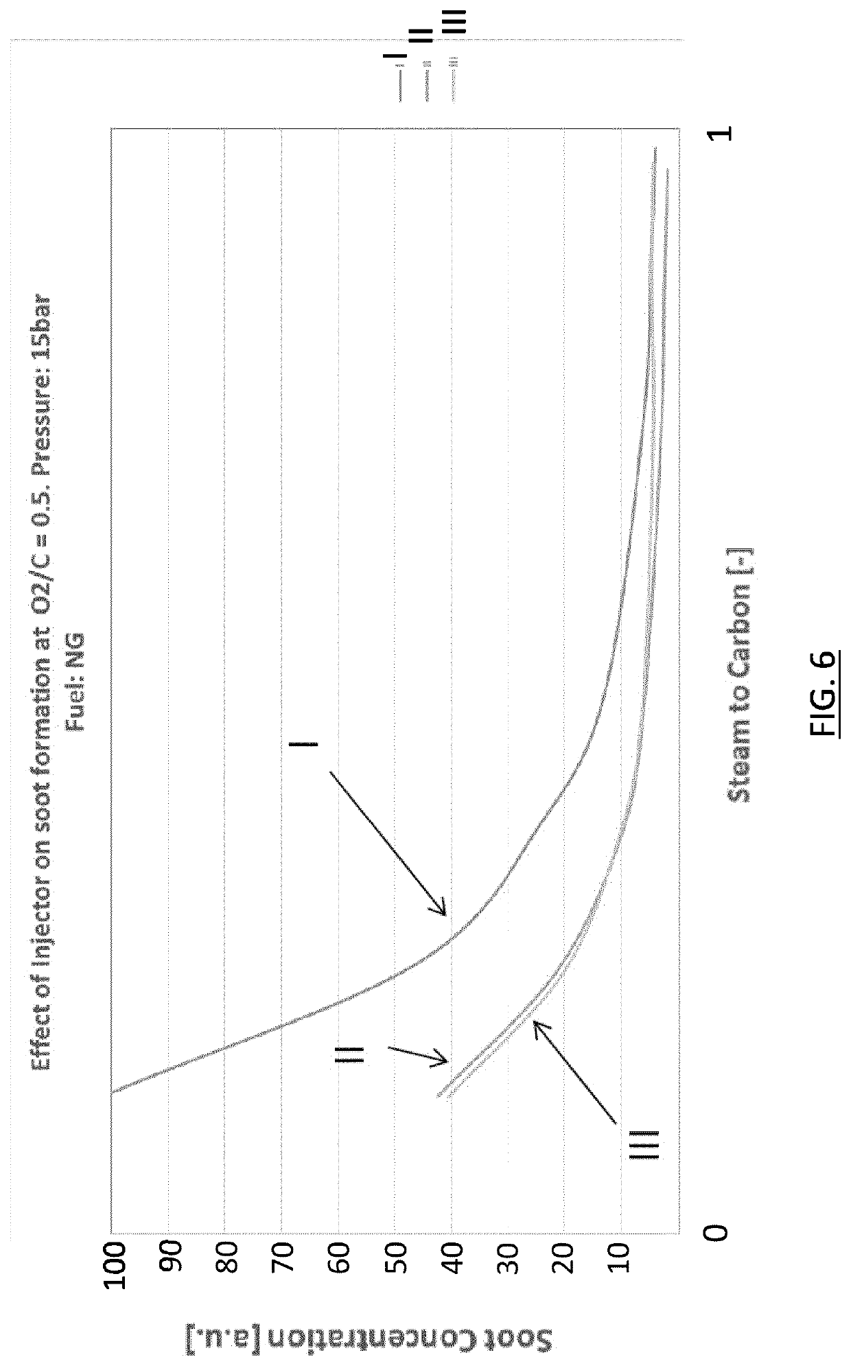
The patent describes a new design for an oxidant nozzle that reduces the formation of soot in a burner compared to previous configurations. By using an elongate nozzle shape with a gradual decrease in cross-section, the oxidant stream is accelerated before it meets the fuel, resulting in better mixing and reduced soot formation. The design also allows for additional combustion space in the fuel channel, resulting in a smaller main combustion chamber and reduced pressure drop. Overall, this new design provides better mixing and reduced soot formation in a more efficient and compact way.

Problems solved by technology

The production of a CO-containing gas from a hydrocarbon source however requires under-stoichiometric combustion which may lead to undesirable formation of soot.
The formation of soot has several drawbacks: loss of carbon source, which is not converted into CO as desired; fouling and obstruction of conduits; need of periodical cleaning which is expensive and disposal of a pollutant and potentially carcinogenic substance.
However increasing the steam to carbon ratio and / or the oxygen to carbon ratio to inhibit soot formation has the disadvantage of increasing the consumption of steam or oxygen, which are valuable source materials.
These techniques and more generally all techniques based on high velocities, swirler and change of directions of the flows have the drawbacks of introducing a significant pressure loss.
In summary, the need to reduce the soot formation forces the adoption of certain operating parameters, such as a large excess of steam / oxygen, or a high velocity and swirl of the streams, which inevitably entail some drawbacks.

Method used


Image

  • Reactor and process for partial oxidation
  • Reactor and process for partial oxidation
  • Reactor and process for partial oxidation

Examples


Embodiment Construction

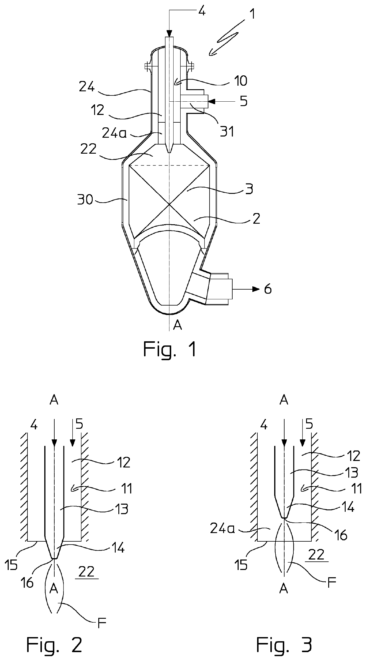
[0059]The figures illustrate an ATR reactor 1 with axis A-A which includes a vessel 30, a reaction chamber 2 inside the vessel 30 and a catalytic bed 3 in the reaction chamber 2.

[0060]The reactor 1 receives a gaseous fuel 5 via a fuel inlet 31 and an oxidant 4 and produces a product gas 6 which is a partially oxidized gas containing H2 and CO.

[0061]The reactor 1 includes a burner assembly 10 fitted to the vessel 30 and installed above the reaction chamber 2.

[0062]The burner assembly 10 includes a single oxidant nozzle 11 located coaxially within a fuel channel 12 of the reactor 1. Particularly, the fuel channel 12 forms an annular pipe around the oxidant nozzle 11, the oxidant nozzle 11 and the fuel channel 12 having a common axis. In the example, the burner assembly is axially mounted and said common axis of the oxidant nozzle 11 and fuel channel 12 is the axis A-A of the reactor 1.

[0063]The fuel channel 12 is delimited by an upper neck 24 of the reactor 1. For example the fuel cha...


PUM


Abstract

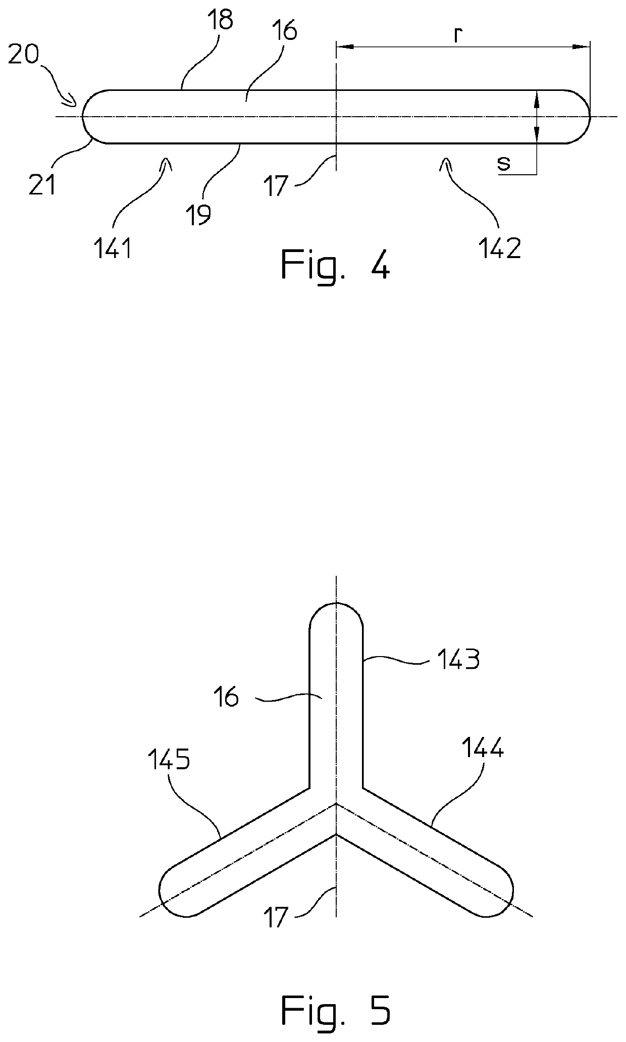
A process of partial oxidation is performed in a reactor which includes a reaction chamber and a burner assembly, wherein: the burner assembly has a single oxidant nozzle located within an fuel channel, said oxidant nozzle comprises a nozzle pipe and a nozzle outlet, the nozzle pipe and the fuel channel are arranged to produce a diffusion flame, the nozzle outlet has a shape with two or more elongate lobes projecting from a center of the nozzle pipe.

Description

FIELD OF THE INVENTION[0001]The invention relates to partial oxidation performed in ATR reactors or PDX reactors.PRIOR ART[0002]Autothermal reforming (ATR) and partial oxidation (PDX) reactors are widely used in the field of production of synthesis gas.[0003]An ATR reactor can be used as a self-standing syngas generation unit or can be used for secondary reforming after a primary steam reforming in a fired furnace. An ATR reactor fed by air or enriched air is often known as secondary reformer. On the contrary PDX systems are an alternative technology typically used to convert a preheated hydrocarbon gas and oxidant.[0004]Autothermal reforming is performed in the presence of a catalyst while partial oxidation is performed in absence of catalyst. The temperature may be around 1000 to 1300° C. for ATR (at the catalyst bed inlet) and even higher (1300° C. or more) for PDX. The pressure is typically in the range 10 to 100 bar.[0005]The ATR and PDX reactors include a burner, which is norm...

Claims


Application Information

Patent Timeline
IPC IPC(8): C01B3/36F23D14/58
CPCC01B3/363F23D14/583C01B2203/0244F23D2212/20C01B2203/0872F23D2203/101F23D2212/10C01B2203/0255
Inventor ZANICHELLI, LUCACOLMEGNA, GIACOMO
Owner CASALE SA
Learn More