Method and apparatus for heating glass melting furnaces with fossil fuels

Inactive Publication Date: 2005-03-08
BETEILIGUNGEN SORG
View PDF5 Cites 3 Cited by
  • Summary
  • Abstract
  • Description
  • Claims
  • Application Information

AI Technical Summary

Benefits of technology

An object of the invention is therefore to present a cascade heating system for glass melting furnaces, in which the formation of soot and graphite is reduced as far as possible or prevented completely, without an inadmissible increase in the nitrogen oxide content in the waste gases from the furnace.
This object of the invention is accomplished completely by these solutions. Initially the secondary fuel, which has a lower linear momentum than the primary fuel supplied through the primary burners, is supplied through the side burners, the cascade burners, in the lee of the step or step wall, which can also be described as a “baffle wall”. The soft and wide cascade flame thus created covers the primary flame(s) of the underport firing across the complete port neck width and reduces the core temperature of the primary flame considerably, which results in a reduction in NOx formation.
However, the additional provision or inlet of secondary oxidation gas in the step results in the following additional unexpected advantages:prevention of soot or graphite and, if necessary, the oxidation of these carbons,afterburning of CO and other carbon compounds,use of individual fan control to influence the effect of the secondary oxidation gases.
As a result of further embodiments of the apparatus according to the invention, it is particularly advantageous if, either individually or in combination:an oxidation gas lance is provided in the center of the secondary burner for the supply of secondary oxidation gas into the step,an oxidation gas lance is provided in the side wall outside of the secondary burner for the supply of secondary oxidation gas into the step,at least one opening for the supply of secondary oxidation gas into the step is provided in the bottom of the step, in particular if the at least one opening is provided immediately in front of the wall of the step,at least one opening for the supply of secondary oxidation gas into the step is provided in the wall of the step,at least one opening for the supply of secondary oxidation gas into the step is provided in both the bottom and the wall of the step,a refractory block is provided on the step at the end of step opposite the secondary burner to protect the side wall of the port neck from the flame from the secondary burner, and / or, ifvariable fans are provided for the supply of the secondary oxidation gases into the step.

Problems solved by technology

The main problems in the construction and operation of glass melting furnaces concern not only a reduction in the specific energy consumption per ton of glass (energy optimization), but also a reduction in the environmental emissions and retention of the furnace condition.
However, if sub-stoichiometric (fuel rich) conditions exist in or near the flame, soot is formed that is deposited in the area of the burner ports or port necks.
On the other hand, undesirable soot is formed locally.
The combustion air has the tendency to divert the flame from the cascade burner shortly after entry into the combustion chamber, thereby making it more difficult to mix the gases in the flames.
However, it has been shown that, as a result of the lack of air in the rolling flame, soot is formed which is deposited as an increasingly thick graphite layer in the stepped area.
The regenerator is normally connected to a high-voltage electrostatic precipitator, and graphite particles which finally reach the electrostatic precipitator cause short circuits.
However, operation of such systems has shown that soot deposits form in the burner ports and in the steps on the firing side, where the soot deposits sinter to form graphite layers.
Alternating firing reversal takes place in such furnaces, which can be either U-flame or cross-fired installations, and these graphite layers tend to break off as a result of thermal deformation when the firing is reversed, so that graphite splinters collect in the regenerators.
These splinters are swept by the high velocity waste gases into the electric particle separator connected to the regenerator, where they can cause short circuits.
This known solution is neither intended for nor is it suitable for this.

Method used


Image

  • Method and apparatus for heating glass melting furnaces with fossil fuels
  • Method and apparatus for heating glass melting furnaces with fossil fuels
  • Method and apparatus for heating glass melting furnaces with fossil fuels

Examples


Embodiment Construction

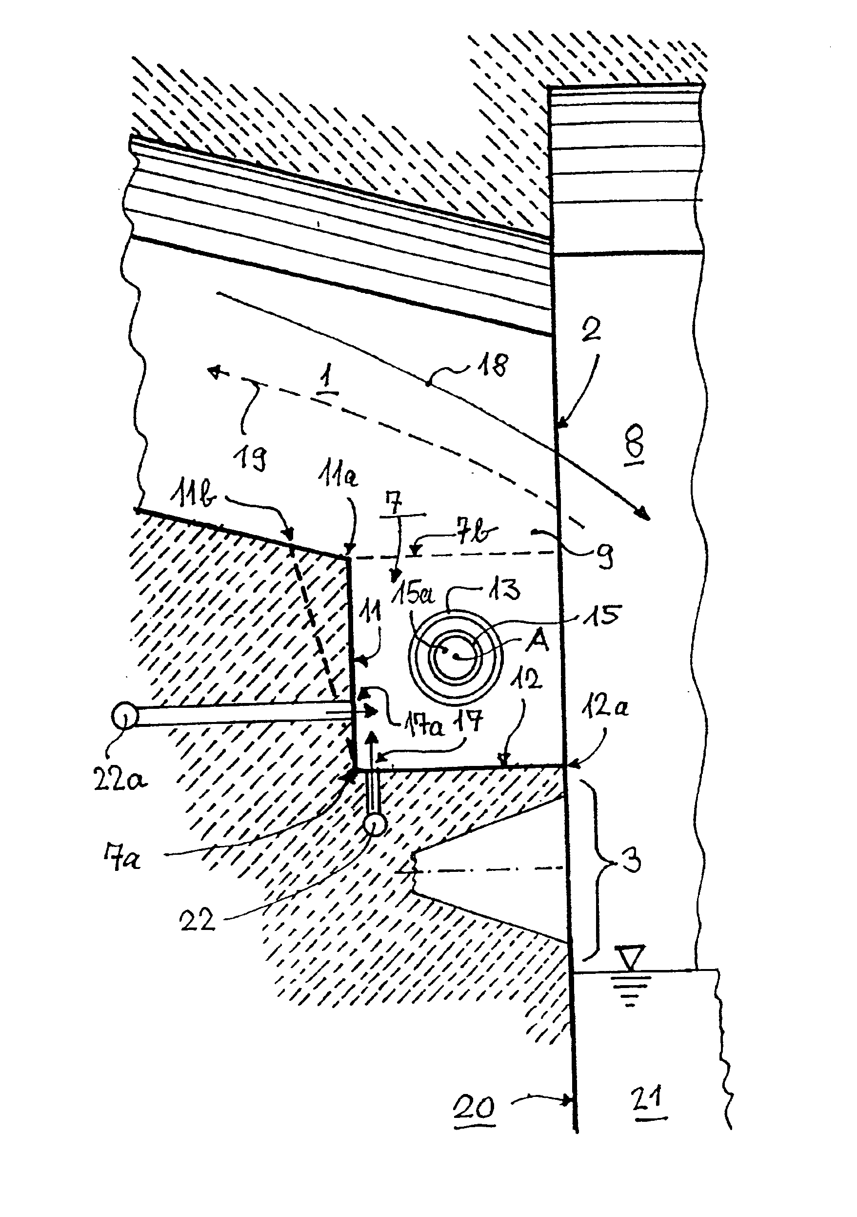
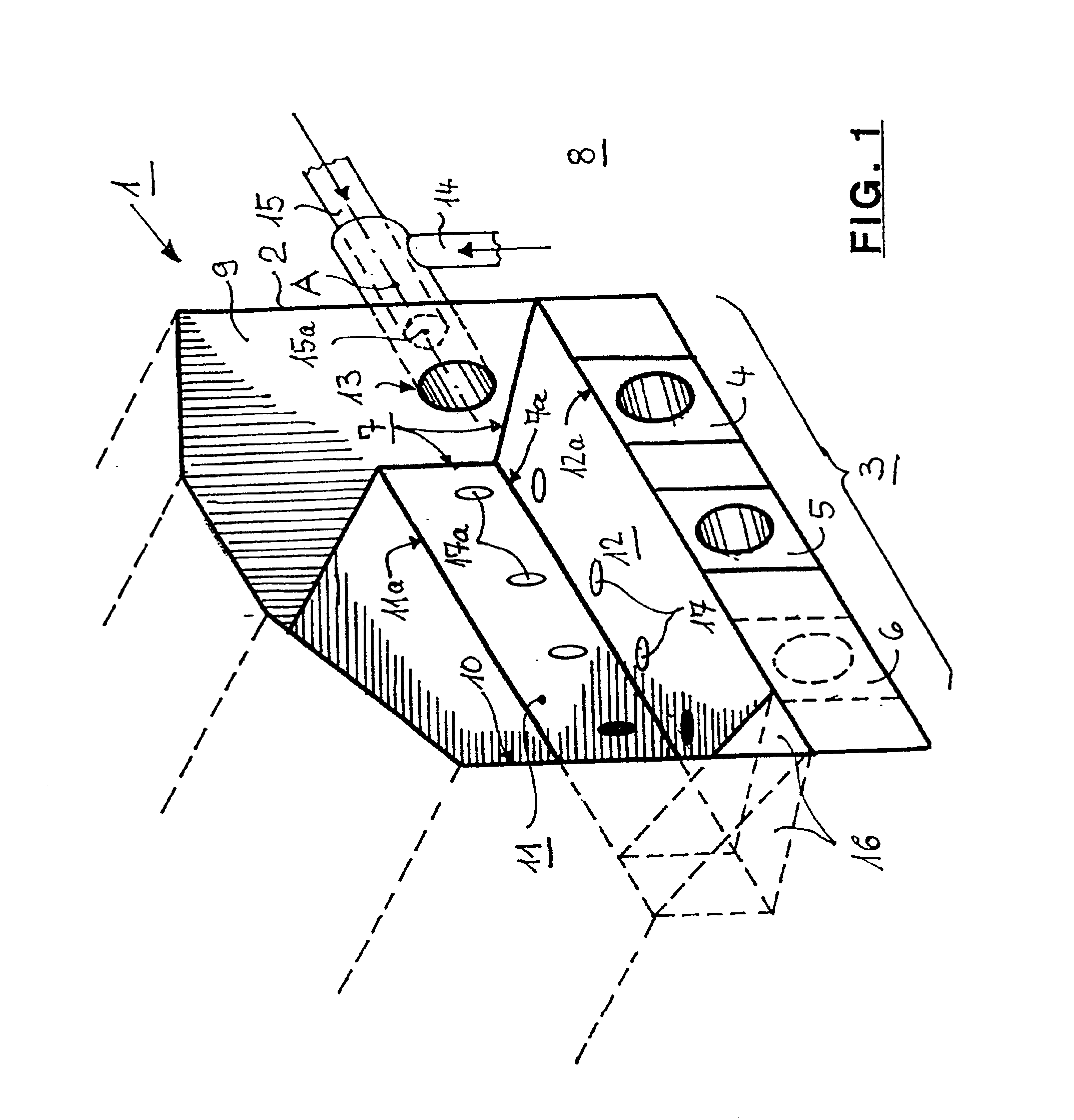
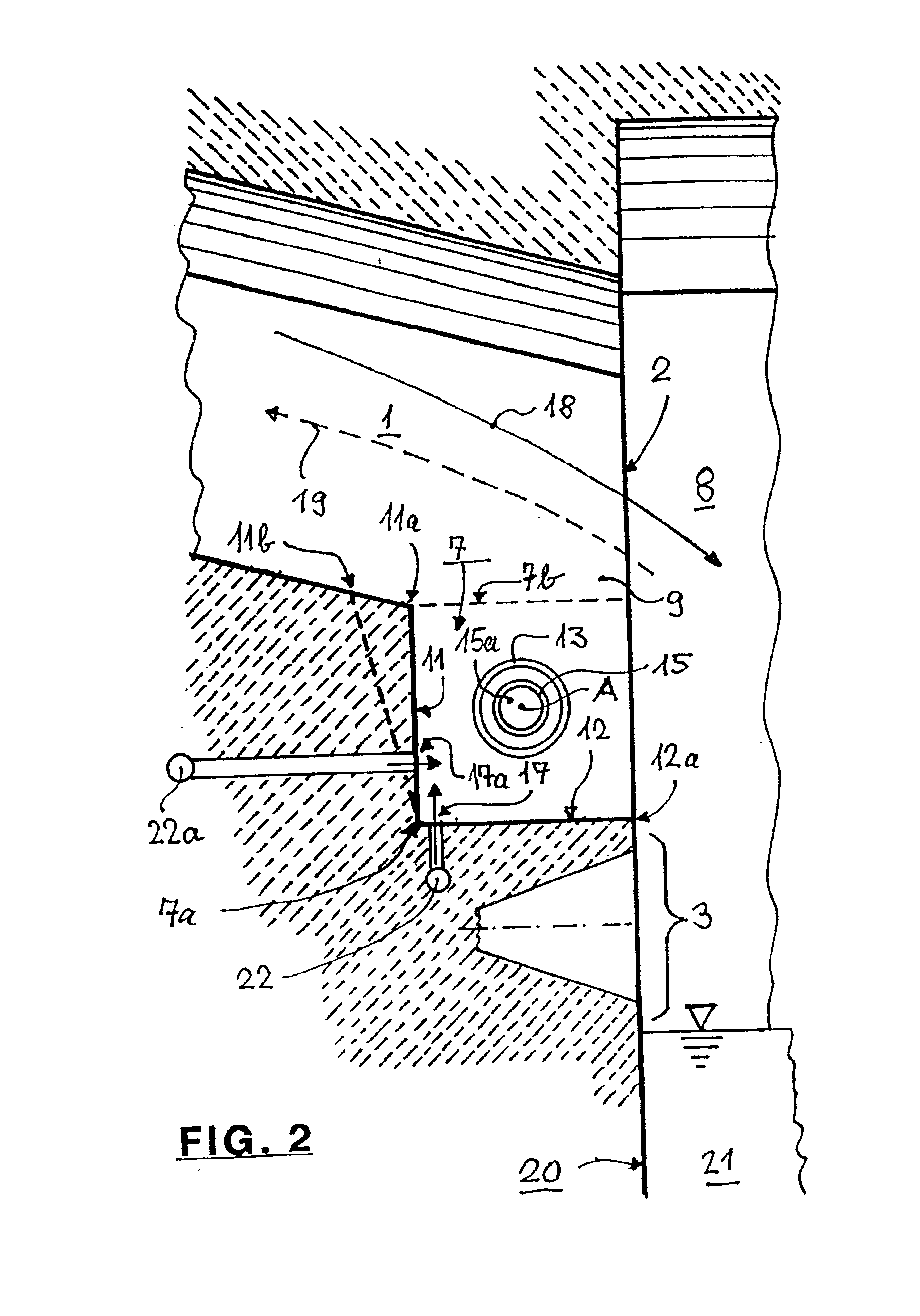
FIG. 1 shows a port neck 1 with a port mouth 2 and its internal surfaces. The port neck 1 has under-port firing 3 of a known type, in which either two primary burners 4 and 5 are installed asymmetrically (offset to the outside from the furnace axis) or three primary burners 4, 5 and 6 are installed symmetrically, whereby only the corresponding burner blocks are shown. The primary burners comprise burner nozzles, not shown in the figure, installed behind these burner blocks for the so-called primary fuel, the largest portion of fuel. The under-port firing is operated sub-stoichiometrically, i.e., fuel rich, relative to the pre-heated combustion air.

The port neck 1 is connected at the back to a regenerator R1 (indicated by a dash line in FIG. 3) for the preheating of the primary oxidation gas, e.g., from combustion air that flows during the firing phase through this port neck 1 over a step 7 into the combustion chamber of a furnace (not shown). The port neck 1 has an outer side wall 9...


PUM

PropertyMeasurementUnit
Percent by volumeaaaaaaaaaa

Abstract

During the heating of glass melting furnaces having a combustion chamber with regenerators for preheating oxidation gases, with port necks that open into the combustion chamber, with primary burners and with secondary burners that are installed in a cascade arrangement relative to the primary burners, the secondary burners are operated as cascade burners with a relatively low proportion of the fuel, the secondary fuel. Flames are thereby created in over- and sub-stoichiometric conditions and the flame gases formed are mixed with one another so that the complete combustion process in the combustion chamber is more or less stoichiometric. The secondary fuel is supplied by the secondary burners to a step, installed in the port neck. In order to prevent or reduce soot and graphite deposits in the step without increasing the nitrogen oxide content in the furnace waste gases, a secondary oxidation gas is blown into step during the firing phase of each port neck in addition to the primary oxidation gas preheated in the regenerators that flows over the step. If significant deposits of carbon material and / or temperature problems occur, then in a similar way an oxidation gas can be blown in during the exhaust phase for the furnace waste gases of each port neck when the secondary burner is switched off.

Description

This application claims priority for application P 101 18 880.3-45 filed in Germany on Apr. 18, 2001.BACKGROUND OF THE INVENTIONThe invention concerns a method and apparatus for heating glass melting furnaces.The main problems in the construction and operation of glass melting furnaces concern not only a reduction in the specific energy consumption per ton of glass (energy optimization), but also a reduction in the environmental emissions and retention of the furnace condition. The most polluting components in the waste gases are NOx and CO, both highly poisonous compounds, and also soot and hydro-carbons.In order to provide a better understanding of the problems which arise in glass melting furnaces where air is preheated in regenerators, the following relationships are explained. Pairs of burner ports are operated in a rhythmic reversing cycle. This applies to U-flame furnaces, in which the burner ports are installed adjacent to one another at one end of the furnace, and also to c...

Claims


Application Information

Patent Timeline
IPC IPC(8): C03B5/00C03B5/235C03B5/04C03B5/237F27D17/00
CPCC03B5/2353C03B5/235Y02P40/50
Inventor BECHER, JURGENWAGNER, MANFRED
Owner BETEILIGUNGEN SORG
Why Eureka
Try Eureka